

Gorgar Speaks: How Williams Fitted Pinball Speech into 12 KB
Gorgar (Williams, 1979) stored seven spoken words in 11,968 bytes of ROM using CVSD. This post takes one word of the original ROM data and decodes it live in your browser, using an interactive model of the speech board that you can edit and run.

Nick C
Gorgar was Williams’ revolutionary talking pinball machine. It contained a seven word lexicon, stored on three 4 KB ROM chips, that could be played back into a few short phrases. A sonic experience that would have been mind-blowing to pinball fans in 1979.
Hit Run to hear it. The audio is not played back from a normal sound file, rather it is decoded in your browser from the data in its original format! The long line at the top of the box is the exact bytes of the word “Gorgar” from the machine’s speech ROM, written in base64 so the code on this page can run as is, and the strip below the waveform shows each bit as it is decoded. The box looks short because the work is hidden inside the speechBoard subroutine, a model of the 1979 speech board. The rest of this article opens it up: why speech in 1979 had to fit in a few kilobytes, how CVSD encodes a voice at one bit per sample, and how the MC3417 chip and the filters after it turn those bits back into sound. Each step has its own code box that you can edit and listen to.
Every grey box on this page is editable code. Edit it and press Run (or Ctrl+Enter) to run it again. Reset restores the original.
From chimes to a voice
Until the late 1970s, pinball machines made their sounds with chimes. Whenever a player scored, a solenoid struck a bell. Even Bally’s Mata Hari and Williams’ Hot Tip, both microprocessor-controlled machines from 1977, still relied on chimes.1
That began to change in 1978. Williams’ World Cup went electronic in March,2 and Bally’s Lost World followed in August. The first Williams effects were fairly basic, mostly imitating the chimes they replaced, and were generated by a program just 512 bytes in size. A year later, Flash showed how much more could be done with electronic sound.
Williams had already shown a talking prototype of Disco Fever at the 1978 AMOA show, but the speech was cut before the game went into production. That left Gorgar, released in December 1979, as the first pinball machine to ship with a voice, and 14,000 were made.3 Barry Oursler designed it, Eugene Jarvis did the sound and Paul Dussault did the speech processing. The voice belonged to John Doremus, a Chicago radio personality known for syndicating The Passing Parade, a radio series of short stories about lesser-known moments in history. Williams brought him back in 1982 to voice the villain in its arcade game Sinistar, whose taunt was “Beware, I live!”4
Gorgar’s vocabulary was just seven words: Gorgar, speaks, beat, you, me, hurt and got. A heartbeat sound grew louder the longer the ball stayed in play. Within a year Williams had more talking machines in Firepower and Black Knight, Stern had Flight 2000, and Bally had Xenon. Gottlieb followed in 1981 with Mars God of War.
Fitting speech into 12 KB
All seven words together come to 6.85 s of speech. They live in 11,968 bytes across three ROM chips on the speech board.
In 1979 memory was one of the most expensive parts of a digital design. Wholesale, the cheapest memory chips cost approximately $4 per kilobyte. At that rate Gorgar’s three 4 KB chips cost around $48, although the exact prices Williams paid for memory are unknown.
Using the same encoding as CDs (44.1 kHz, 16-bit, mono), the same audio would require 589.8 KB, or 148 of the 4 KB chips on Gorgar’s speech board, costing a total of $2,368, or $10,895 adjusted for inflation to 2026 prices. Gorgar’s ROMs hold the same seven words in a tiny fraction of that space using smart encoding.
Digital audio
Sound is a variation in air pressure, which a microphone converts it to a voltage. To store it digitally, the voltage is measured at regular intervals (sampling) and each measurement is rounded to the nearest of a fixed set of levels (quantisation).
With n bits per sample there are 2ⁿ levels. Here is one cycle of a sine wave sampled 16 times. The grey line is the original signal, the red staircase is the quantised version, and the shaded area is the quantisation error.
One bit gives two levels, high and low, and the sine wave turns into a square wave. Sixteen bits (CD resolution) give 65,536, and the steps are too small to see at this scale. The CD itself was still in development when Gorgar shipped: Philips demonstrated a prototype in March 1979, and CD players went on sale in October 1982.
Hearing quantisation
The box below contains a recording of me saying “hello”. Like the Gorgar data, it is embedded in the page as base64 (just so it can be printed in the text editor without without loading in some external file). The first lines decode it and combine each pair of bytes into one signed 16-bit sample, low byte first. An uncompressed recording is nothing more than that list of samples.
quantize() reduces each sample to the chosen number of bits. Use the buttons to compare.
At 8 bits the speech is fairly clean. At 4 bits there is audible noise, at 2 bits it is heavily distorted, and at 1 bit it is barely intelligible. Even 4 bits at 16 kHz is 64 kbps, more than four times Gorgar’s 13.98 kbps. Gorgar uses 1 bit per sample and is still intelligible, so it must encode the signal differently.
Delta modulation
Telecom engineers faced the same problem: sending speech digitally with as few bits as possible. Maurice Deloraine at ITT (International Telephone and Telegraph) patented delta modulation in 1946. Instead of each bit saying where the sound is, it says which way the sound is going: 1 means step up, 0 means step down, and the decoder keeps a running total.
Its weakness is the fixed step size. Small steps cannot follow fast changes in the signal (slope overload), and large steps add noise when the signal is quiet (granular noise). In 1970 J. A. Greefkes and K. Riemens at Philips Research addressed this with CVSD, continuously variable slope delta modulation, which adapts the step size as it goes.5 If the last three bits are identical, the output is lagging the input, so the step size increases. Otherwise it decays. The decoder applies the same rule to the same bits, so it reproduces the encoder’s step sizes without any extra data. CVSD became a military standard for digital voice (MIL-STD-188-113, at 16 and 32 kbps).
In the CVSD plot, the three boxed bits are the last three the decoder has seen. When they match, the step size grows for the next bit, and when they don’t, it shrinks back.
Below is a minimal CVSD encoder and decoder in JavaScript, applied to the same “hello” recording. Switch between 1-bit PCM, 2-bit PCM and CVSD. CVSD here samples at 32 kHz, twice the PCM rate, at one bit per sample, so it uses the same 32 kbps as 2-bit PCM at 16 kHz.
At the same data rate, CVSD is clearly intelligible where 2-bit PCM is not. The decoder is the encoder’s tracking loop on its own: both keep the same running estimate.
The decoded output (red) is a staircase, and its sharp edges add high-frequency noise that was not in the original. A low-pass filter passes low frequencies and attenuates high ones, which smooths the steps. Most of what makes speech intelligible is below about 3,400 Hz, the upper limit of a telephone channel. Most of the step noise is above that, so a 3,400 Hz low-pass removes much of the noise and keeps most of the speech. Set lowpass to 3400 to hear it. The same cutoff appears on Gorgar’s speech board.
Reading the speech ROM
Williams did not need to design a decoder: Motorola already sold one, the MC3417, as a telecommunications part.6 The rest is done in software by the Motorola 6808 processor on the sound board. Its speech routine reads a byte from ROM and sends it to the MC3417 one bit at a time over two lines: a data line, and a clock line that tells the chip when to take the next bit.
The routine’s loop takes exactly 64 of the 6808’s clock cycles per bit. Shorter paths through the loop are padded with timing-only instructions, keeping the sampling rate constant just shy of 14 kHz.
Every word in the ROM starts with the byte 0xAA (10101010). Before speaking a word, the routine reads this byte to confirm that the speech ROMs are installed. The byte is also inconsequential to send to the MC3417, as alternating bits instruct the decoder to step up and down by its minimum (effectively holding the output level and doing nothing). A table in the ROM combines the words into phrases, with short pauses between words:
| Phrase | Built from | Probably says |
|---|---|---|
| 0 | word1, word2 | ”Gorgar speaks” |
| 1 | word3, pause, word4, pause, word1 | ”You beat Gorgar” |
| 2 | word6, word1, pause, word4, word6 | ”Me Gorgar, beat me” |
| 3 | word3, pause, word4, pause, word6 | ”You beat me” |
| 4 | word3, pause, word7, pause, word1 | ”You hurt Gorgar” |
| 5 | word5, pause, word7 | ”Me hurt” |
| 6 | word5, pause, word8, pause, word3 | ”Me got you” |
| 7 | word1 | ”Gorgar” |
| 8 | everything, in order | the self-test |
The table has eight word entries but the ROM holds only seven recordings. Word 5 and word 6 are both “me”, and both start at the same ROM address. One plays the full recording, the other stops partway through and gives a shorter “me”. The second “me” costs no extra ROM.
Modelling the speech board
Decoding
The bit stream goes to the MC3417 on the speech module, shown here on the Williams schematic dated October 1979:7
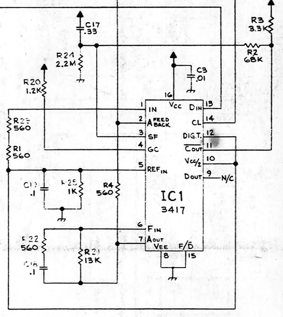
The MC3417 is the CVSD algorithm built in analogue circuitry, with its timing set by the resistors and capacitors around it:
- When the last three bits match, the chip turns on its coincidence output, pin 11. This is the three-in-a-row rule.
- The step size is set by the voltage on C17. C17 charges through R2 while pin 11 is on, increasing the step size, and discharges when it is off, decreasing it. The time constant, R2 × C17, is 22.4 ms, roughly the length of a syllable (you can shrink the value of R2 in the code to break this and hear the consequences).
- R24 sets the minimum step size.
- R21, R22 and C16 form a leaky integrator that reconstructs the waveform. Each step comes out as an exponential ramp rather than an instant jump, and the output decays toward zero, so errors fade out instead of accumulating.
The code below models the MC3417 with the part values from the schematic and uses the same bytes as the first box.
Filtering
That is the raw MC3417 output, a staircase whose sharp corners add high-frequency noise. The rest of the speech module filters it before it joins the game’s sound effects. The schematic gives the part values but not the reasoning, so what follows is a reading of the design.
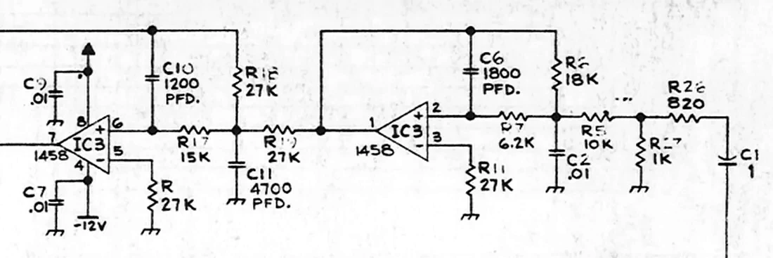
C1 blocks the chip’s DC level and anything below 92 Hz. Then come two op-amp low-pass stages, the two halves of a 1458 dual op-amp. Two stages in a row cut the noise far more than one, about 49 dB at the 13.98 kHz bit rate against about 24 dB for one, so you would expect two identical stages. Instead they use different parts and cut off at 3,551 Hz and 3,330 Hz.
The reason is attenuation. R26 and R27, the resistors around C1, form a divider that drops the signal to 0.55 of its level, and stage 1 makes this up with a gain of R6/R5 ≈ 1.7, bringing the chain back to about 0.95. In this kind of filter the resistors that set the gain also set the cutoff, so stage 1 had to be designed around its gain, while stage 2, at unity gain, could use equal 27 kΩ resistors. Both were most likely aimed at 3.4 kHz, the top of the telephone voice band, and the 6% gap between them is within the tolerance of 1979 parts.
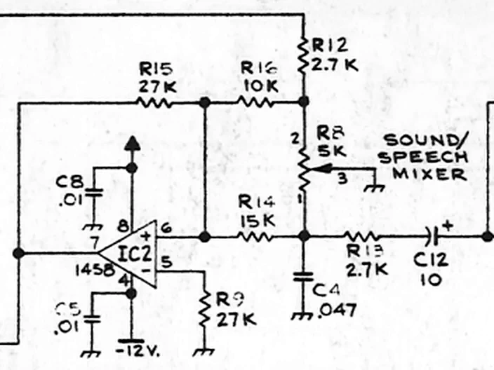
The last filter is stranger still. At the mixer, R13 and C4 form a low-pass, and the sound/speech pot R8, which sets how loud the speech is against the game’s effects, is wired from the same point to ground. That makes the pot part of the filter, so turning the speech down raises the cutoff, from 2.2 kHz with speech fully up to 2.8 kHz at mid travel and higher beyond. It looks like a side effect of using one set of parts as both the filter and the volume control.
Pick a point in the chain below to hear the speech there. Listen after C1 and the noise is still there, and after stage 2 it has gone. Move the pot and watch the mixer’s curve move with it.
With the pot at its midpoint, the combined response is within 1 dB of flat from 300 Hz to 1 kHz, 2.7 dB down at 2 kHz, 9.7 dB down at 3.4 kHz, and 62.8 dB down at the 13.98 kHz bit rate.
What happened next
Williams used CVSD speech for over a decade, from Black Knight through System 11 games like Road Kings and into the early WPC machines. Twilight Zone was planned as the first game on a new sound system, but shipped with the CVSD board because the new system was not ready. That new one, DCS, arrived in 1993 with Indiana Jones: The Pinball Adventure and Judge Dredd, by which time memory was cheap enough for compressed sampled audio. CVSD is still in use: it is one of the voice codecs in the Bluetooth standard.
Thanks to PinMAME (master branch, checked 15 October 2026), whose Williams sound board code, src/wpc/wmssnd.c, provided the ROM memory map and the wiring between the 6808 and the speech chip, with the speech data and clock on two PIA lines. This model was also checked against a re-implementation of PinMAME's earlier floating-point HC55516 decoder and its C-8228 filter, and the two produce closely matching speech, with a correlation of about 0.95.
The two differ in the hardware they model. PinMAME emulates Gorgar's speech with an HC55516 and the filter from Williams' C-8228 speech board. This post models the MC3417 board from the 1979 Williams schematic. The main effect is on the step size, which adapts with a time constant of 22 ms (R2 × C17) rather than the 4.6 ms of PinMAME's HC55516 model.
The filtering differs as well. Both boards use two op-amp low-pass stages, and the second stage is identical on each, cutting off at 3,330 Hz. The first stages use different parts and cut off at 3,473 Hz in PinMAME's C-8228, and 3,551 Hz on the 1979 board. PinMAME also does not model a high-pass in front of the filters, or the mixer's low-pass and sound/speech pot.
The Gorgar ROM excerpt and the schematic sections are short extracts, used here for education and historical reference. They remain the property of their rights holders. To request removal, get in touch.
Footnotes
PinWiki, Williams System 3 - 7 (Hot Tip, November 1977, with chimes). ↩
Pinpedia, Gorgar, which gives production from late November 1979 to March 1980. ↩
Wikipedia, John Doremus. ↩
J. A. Greefkes and K. Riemens, “Code modulation with digitally controlled companding for speech transmission”, Philips Technical Review, 1970, pp. 335–353. ↩
Motorola, Telecommunications Device Data, DL136 (1984). ↩
Williams Electronics, Schematic, Speech Module, dated 10-1-79, available from the Internet Pinball Database entry for Gorgar. ↩
Share this post
Like this post? Share it with your friends!