
Does a Lower Resistance Pinball Coil Hit Harder?
Lower resistance means more power, says the forum rule. We measured 26 AWG coils to see how much unwinding really helps, and where it stops.

Nick C
Your slingshots feel a bit limp, so you ask on Pinside how to get more out of them. Two answers come back pretty quickly. One: look at the resistance, lower is stronger, so fit a lower resistance coil. Two: save yourself the money and pull a few turns off the one you’ve got.
Both answers are sort of right. They come from the same simple sums. We had a heap of coils on the bench for our coil chart, so we checked. The short version: on paper, pulling turns off a coil buys you a little more strength for a lot more heat. But a real coil isn’t as simple as those sums make out, so even that is only part of the story. And if a coil that used to be fine has gone limp, the fix is usually mechanical, not electrical.
Is lower resistance really more powerful?
Resistance, measured in ohms (Ω), is how hard the coil pushes back against the current. Lower resistance means more current, and between stock coils the forum rule mostly holds. An AE-23-800 at 3.8 Ω hits a lot harder than an AE-26-1200 at 10.4 Ω, and an AE-30-2000 at 38.5 Ω is a gentle thing by comparison.
But the rule only works because the manufacturers have already done the hard part. Every stock coil is a balance between how hard it hits and how hot it gets. Thicker wire lets them build a strong coil that doesn’t cook itself, and thicker wire happens to have lower resistance. So the low resistance is a side effect of a stronger design, not the reason it’s strong. Lower the resistance some other way and the rule starts to wobble.
What does the plunger actually feel?
Inside any solenoid, such as a pinball coil, sits a lump of iron called the armature. In pinball speak we usually call it the plunger. It’s the bit that actually moves, and it’s what kicks the slingshot or swings the flipper. When current flows through the coil, the coil becomes an electromagnet. Its magnetic field pulls the plunger in.
How hard the coil pulls comes down to two things: how much current is flowing through the wire, and how many times the wire goes round.
Think of the current as runners on a track wrapped round the plunger, with the magnet counting laps. One runner doing 1000 laps gets the same count as ten runners doing 100 laps. Current times turns is called ampere-turns, and in the simple picture it’s what sets how hard the plunger gets yanked in. Resistance just decides how many amps you get.
At 48 V, the AE-23-800 manages about 10200 ampere-turns and the AE-26-1200 about 5500. The 23-800 has fewer turns, but its thicker wire lets nearly three times the current through, so it wins comfortably.
Those numbers come from what we’ll call the simple model. It’s a handy way to compare one coil with another ignoring the inductance.
Current is voltage divided by resistance, then multiply by the number of turns.
AE-23-800: 48 V ÷ 3.77 Ω = 12.7 A. 12.7 A × 800 turns ≈ 10200 ampere-turns.
AE-26-1200: 48 V ÷ 10.4 Ω = 4.6 A. 4.6 A × 1200 turns ≈ 5500 ampere-turns.
That's the simple model. It treats the coil like a light bulb: voltage in, current out, done. It also assumes a cold coil and a perfect power supply.
But a coil isn't a light bulb. It's an inductor, so the current can't jump straight to its final value. It builds up over the pulse, at a rate set by the coil's inductance, and the plunger moving through the coil holds it back even more. The plunger does its moving while the current is still building. So these figures are the ceiling a coil would reach if it were left switched on, not what happens in a real hit. For what actually happens during a pulse, see Part 5 of our flipper history series.
Does removing windings make a coil stronger?
This is the forum hack. Unwind some turns, the resistance drops, more current flows, and the coil feels punchier. Many of us who like to get our hands dirty have tried this hack at some point, me included, and it does work.
We could go unwinding a coil to get the measurements needed, but coils already come in the same 26 AWG wire with different numbers of turns, all on the same size bobbin, and we had three of them on the bench: 1200, 1400 and 1500 turns. Line them up and measure them, and we get an idea of what taking a few hundred turns off does.
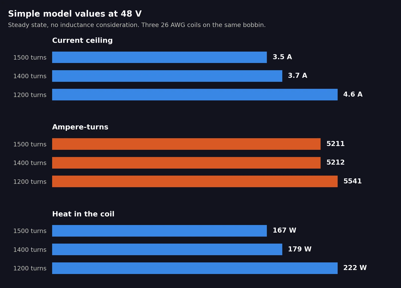
The simple model: steady-state figures for 26 AWG coils at 48 V. From 1500 turns down to 1200, resistance falls from 13.8 Ω to 10.4 Ω, current rises from 3.5 A to 4.6 A, ampere-turns from about 5200 to 5500, and the heat the coil gives off from 167 W to 222 W. Those watts are heat, not punch: it’s electrical power the coil turns into warmth while it’s switched on.
In the simple model, going from 1500 turns down to 1200, the current goes up by about a third. So does the heat. The ampere-turns go up by only about 6 %.
On paper, that’s a small gain for a lot more heat. And remember these are the figures a coil would settle at if it were left switched on. In a real hit the plunger moves while the current is still building, so the simple model can’t tell you how much harder the 1200-turn coil really hits. The extra current and heat are steady-state figures too, so treat them as a rough guide, not a measurement.
Now look at the 1400 and the 1500. The simple model says the 100 extra turns should cost the 1500 a couple of percent in ampere-turns. On our bench they cost almost nothing, because the two coils have near enough the same resistance per turn. That isn’t a measuring error. It’s the catch with using different coils to stand in for unwinding one. Magnet wire is made to a tolerance, and a coil wound from wire that’s a touch thicker has a touch less resistance, easily enough to hide a couple of percent. The 1500 is heavier than its turn count alone would suggest, which fits. Unwind your own coil and that doesn’t come into it, because it’s the same wire before and after. What the comparison does show is how small the effect of 100 turns is.
Why does unwinding work at all?
This bit is odd. In the simple model, take half the turns off and you halve the resistance, so twice the current flows. Twice the runners, half the laps. The magnet’s count hasn’t changed, so on paper unwinding should do nothing.
Part of the gain comes from the shape of the coil. The turns you pull off are the outside ones, and like the outside lane of a running track, they’re the longest laps. The inner turns are wrapped tight round the middle and use much less wire each. Strip the outer layers and every lap that’s left is a bit shorter, so the resistance drops a little faster than the turns do.
A real coil adds two more effects, and they pull in opposite directions. Fewer turns means less inductance, so the current builds up faster and arrives sooner in the pulse. But the pull on the plunger doesn’t come from the current alone. It comes from the coil’s inductance changing as the plunger moves in, and a coil with fewer turns has less of that to give, so each amp pulls less. Which effect wins depends on the pulse, the coil and the mech it’s bolted to. The simple model can’t tell you. That’s why our coil chart measures inductance as well as resistance.
Why does it stop working?
Now take the idea to its theoretical extreme. Imagine coils with fewer and fewer turns, all the way down to zero. What’s left is just a length of wire. Every wire has a bit of inductance, but a straight wire makes a hopeless electromagnet. Put it across 48 V and it draws a huge current, pops the fuse and moves precisely nothing. So somewhere between a stock coil and a bare wire, the gains run out. Three things get in the way.
The rest of the machine. The power supply, wiring, connectors, driver board and fuse all have a bit of resistance of their own (supply resistance). Think of a thin hose feeding a fat nozzle. For a 10 Ω coil, a fraction of an ohm elsewhere doesn’t matter. For a 2 Ω coil it matters a lot, and it swallows the extra current. So in the simple model there’s a sweet spot for the number of turns, and below it the coil gets weaker again.
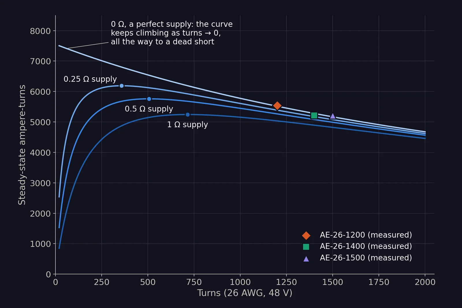
What the simple model predicts if you could wind a 26 AWG coil with any number of turns and run it at 48 V. The top line is a perfect power supply, where fewer turns always means more ampere-turns. The lower lines add a little resistance in the rest of the machine (0.25, 0.5 and 1 Ω, made-up examples, not measured), and that changes the story: each curve now peaks, at about 360, 510 and 720 turns, and below that the coil gets weaker fast. Our three coils sit out at 1200 to 1500 turns, where the curves are almost flat, so taking turns off buys very little. Steady state only, no inductance.
Look where those sweet spots are: about 360 to 720 turns, hundreds of turns fewer than a 26-1200. Even in the simple model, and even right at the sweet spot, a 26 gauge coil only gets around 4 to 15 % more ampere-turns than a 26-1200, and the more tired the wiring and connectors, the less that gets. That’s the ceiling for the whole idea, not a target. Taking a couple of turns off gets you a small slice of it.
It’s no accident that the 26-1200 is one of the most common playfield coils around. It sits where the curve has already flattened: go with fewer turns and you gain a few percent in ampere-turns at best, while the current and heat keep climbing. For coils that have to work frequently, like slingshots and pop bumpers, that heat adds up, so 1200 turns is a sensible value.
The iron saturates. The iron plunger is what concentrates the coil’s magnetic field and makes the pull strong, but iron can only carry so much field. Once it’s saturated, pushing more current through the coil adds very little extra pull. Our LCR meter measures with a tiny test current, so it can’t show where that point is for these coils, but it puts a ceiling on what extra current can buy.
Heat. Compare two stock coils in the same 26 gauge wire: a 26-1500 and a 26-1200. The 26-1200 turns a third more power into heat, in about a quarter less copper, so it heats up about 75 % faster. Those are steady-state numbers again, so they ignore inductance and a real pulse won’t match them exactly. Real heating still scales the same way, though. For a player, that’s the bit that matters: a coil that fires a lot, like a slingshot in a busy game, gets hot sooner, and a hot coil fades.
Should you change the coil at all?
Probably not, to be honest. The game left the factory with a coil chosen for that job, and when it was new, it did the job. If the ball isn’t getting where it should any more, the coil is rarely the thing that’s changed. Much more likely, something mechanical has worn or gummed up and the coil is fighting it. So before you reach for a stronger coil or the wire cutters, check:
- Bushings and pivots. Anything that rotates, like a flipper shaft in its bushing or the pivots in the linkage, should turn freely with no slop. Worn bushings are one of the most common causes of weak flippers, and our bushing replacement guide walks through the fix.
- The coil sleeve. That’s the tube the plunger slides in. Over time it gets mucky inside. The plunger’s corrosion-resistant plating gets hammered against the coil stop on every hit, and the bits that come off build up in the sleeve along with dust and debris. Clean it out, or swap it if it’s worn, so the plunger slides freely.
- The plunger. It should be clean, smooth and free of rust or corrosion. Check the end that hits the coil stop too: years of hammering can mushroom it out so it catches in the sleeve. A rough plunger in a tired sleeve loses a lot of pull to friction.
- The coil stop. That’s the fixed lump of iron at the far end of the coil that the plunger slams into. It wears with every hit, and the plunger travels a little further each time. It can get so bad that the linkage starts hitting the other end of the coil before the plunger seats properly, and the whole stroke goes mushy.
- Anything fouling. Loose wires, a bent bracket, a spring rubbing on something. Work the mechanism by hand with the power off. It should move smoothly all the way and snap back.
- The coil wrap. Look at the paper or tape wrapped round the outside of the coil. Dents, gouges or impact marks mean it’s taken a knock, usually a slipped screwdriver or a dropped tool during maintenance. If it’s brown, scorched or melted, it’s been cooked at some point.
That last one ties back into everything above. The wire is only insulated by a thin enamel coating. A knock hard enough to dent the winding, or enough heat, can break through it, and two neighbouring turns end up touching. That’s a shorted turn. You might think it’s just free unwinding, one less turn and a bit less resistance. It isn’t. The shorted turn becomes a little closed ring of copper sitting inside the coil, and every time the coil fires it fights back against the rest of the winding. The coil ends up weaker and runs even hotter. Resistance won’t show it, but an inductance meter will, and there’s more on that in what to do when the label’s missing or wrong.
If everything here looks good, and you still want a bit more oomph, read on.
So which coil should you use?
- Picking between stock coils: lower resistance at the same voltage is a fair shortcut for “hits harder”. The manufacturer has already made sure it can take the heat.
- Want more punch? Fit the next stock coil up rather than unwinding the one you’ve got. An AE-25-1000 gives about 6850 ampere-turns at 48 V in the simple model, against the AE-26-1200’s 5500, and its thicker wire is made to take it.
- Unwinding anyway? Most people take a couple of turns off, as the forums suggest. On a coil with a thousand or so turns that’s a small change: the resistance drops a little, the current and heat go up a little, and so does the punch. Don’t expect a transformation.
- Running closed loop? A current-regulated driver like Octane sets the current itself and holds it there, so resistance mostly stops mattering. With the current fixed, fewer turns just means less magnet, so unwinding makes the coil weaker, not stronger. That’s why Octane coils are deliberately over-specified in the first place.
Steady-state DC only. There's no inductance anywhere in these equations, so they describe a coil left switched on, not a real hit.
Same gauge throughout: wire cross-section a, resistivity ρ, N turns with a mean turn length ℓ(N).
Coil resistance: Rc = ρ·N·ℓ(N) / a
Ampere-turns, perfect supply: NI = N·V / Rc = V·a / (ρ·ℓ(N)). N cancels, so the only gain from fewer turns is the shorter mean turn.
With supply resistance Rs: NI = N·V / (Rs + ρ·N·ℓ(N)/a). As N → 0, NI → 0. With ℓ = c + kN this peaks at Nopt = √(Rs·a / (ρ·k)). The Rs values in the chart are examples, not measurements.
For the inductance side, which is what a real pulse depends on, see our coil chart.
Share this post
Like this post? Share it with your friends!