
A Technical History of the Pinball Flipper [Part 1]: The Mechanically Switched Flipper
From the first electromechanical flippers of 1947 to the survival of full power, mechanically switched flipper control well into the early solid-state era.
Introduction
The obvious way to divide the history of the pinball flipper is by the technology of the machine around it, electromechanical against solid-state. For the flipper itself, that division is misleading. The boundary that actually matters is one of control. For the first several decades the full power of the flipper coil was carried and routed by mechanical contacts, namely the cabinet button and the end-of-stroke (EOS) switch. Only later did electronics take over that work and demote the switches to mere inputs. That control boundary does not fall where the microprocessor arrives. As this article will show, the mechanically switched flipper survived for years inside machines whose game logic had already gone solid-state. Part 1 therefore covers the whole of that period, from the birth of the flipper in 1947 to the point, in the late 1980s and early 1990s, at which the industry finally took flipper power off the switch.
By “mechanically switched” we mean that the high coil current physically flows through, and is reconfigured by, mechanical contacts. This was true of every electromechanical (relay-logic) game, and it remained true of the flipper circuit in most early solid-state games long after relays had vanished from the rest of the machine.
The birth of the flipper, 1947
The flipper as a player-controlled device arrived with Gottlieb’s Humpty Dumpty, released on 25 October 1947, designed by Harry Mabs with artwork by Roy Parker, in a production run of roughly 6,500 units . It is worth being precise about what was new. Sprung bats had appeared earlier on mechanical baseball games, operated by hand. What Mabs introduced was the electromechanically actuated, player-controlled flipper, fired by a solenoid when the player pressed a cabinet button. Gottlieb called these devices “flipper bumpers,” a term that has since fallen out of use.
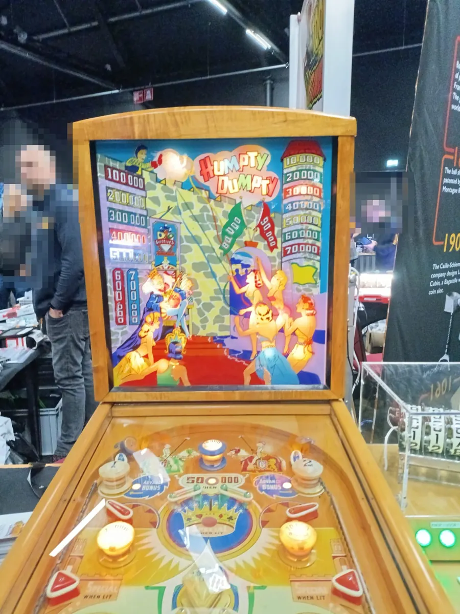
Humpty Dumpty carried six of these flippers, roughly two inches long, arranged around the perimeter of the playfield and, unlike anything built today, facing outward, away from the centre. The early coils were comparatively weak, which is part of the reason six were needed to keep a ball in play. Pinball historians often note that Gottlieb never sought a patent on the flipper itself. Whatever the motivation, the absence of an enforced monopoly meant the idea spread across the industry within a single season.
Two flippers at the bottom, 1948
The configuration now thought of as obvious, a pair of flippers guarding the drain at the foot of the playfield, was not obvious at all in 1947. It was Steve Kordek who arrived at it . Standing in for Genco’s ailing lead designer, Kordek reduced the six-flipper idea to two and placed them at the bottom of the playfield for Triple Action (Genco, 1948, not to be confused with the 1973 Williams title of the same name ), demonstrated at the January 1948 Chicago trade show . The detail that most popular accounts get wrong is the geometry. Triple Action’s two flippers still faced outward, and they were pulsed in unison rather than controlled independently. The inward-facing, independently operated layout used today evolved over the following couple of years rather than appearing fully formed.
Kordek’s less celebrated but arguably more important contribution was electrical. Under Kordek, Genco drove its coils with direct current at roughly 18 volts, at a time when this was unusual in the trade. Gottlieb, Williams, and Bally all ran their solenoid circuits on raw AC, typically 24 to 50 volts straight from the transformer. Genco’s DC came from a selenium rectifier mounted directly on the transformer, converting the AC output before it reached the coils .
The selenium rectifier was an early solid-state device, a stack of iron plates coated with a thin selenium film that conducted current in one direction only. It predated the silicon diode by years and was bulky, inefficient, and, as every restorer eventually discovers, doomed. Selenium rectifiers do not fail suddenly. They degrade. Over time the forward voltage drop creeps upward and the internal resistance climbs, so the DC output sags. Flippers weaken. Score reels reset sluggishly. Ball release mechanisms hesitate. Then the rising resistance heats the stack, and the selenium begins to burn, releasing a smell so foul and persistent that it is the single most commonly cited sensory memory in pinball restoration. It is not a question of whether a selenium rectifier will fail, but when. Every surviving Genco game of this vintage has either had its rectifier replaced or needs it done.
The reason nobody else used DC is simple: it was an extra component, an extra failure mode, and an extra cost, all to solve a problem that most manufacturers did not think they had. AC solenoids worked. But AC drive delivers a force that varies with the mains cycle, peaking and dipping 50 or 60 times a second. DC drive is steady. The pinball author Roger Sharpe has argued that this mattered as much as the two-flipper layout itself, because DC drive gave the flipper a consistent, controllable kick, so that a ball struck cleanly from the bottom could be sent the full length of the playfield with some accuracy . Skill-based play, in other words, depended not only on where the flippers sat but on how cleanly the coil could be made to deliver its force.
The modern geometry settled quickly thereafter. Gottlieb’s Just 21 (January 1950) is generally cited as the first game with two inward-facing flippers, though they sat well apart to make room for a turret ball shooter at the bottom centre. Gottlieb’s Spot Bowler, later the same year and a Wayne Neyens design, brought the two inward-facing flippers close together in the now familiar arrangement . Bat length grew more slowly. The industry kept to two-inch flippers until the late 1960s, with Williams introducing the three-inch flipper on Hayburners II in 1968.
Inside the mechanically switched flipper: the dual-wound coil
A solenoid that must deliver a hard, brief kick and then hold the flipper up indefinitely faces a contradiction. The kick needs high magnetomotive force, which means high current, but sustaining that current would overheat the coil within seconds. The answer was the dual-wound flipper coil, two windings on a common core. A low-resistance “power” (or “switching”) winding provides the strong pull of the power stroke. A higher-resistance “hold” winding draws far less current and is just strong enough to keep the flipper raised . The contemporary patent literature is explicit that a single winding was not, at the time, considered capable of doing both jobs. A flipper coil therefore carries three solder lugs rather than the two of an ordinary solenoid, a feature still used to identify one on a bench .
The remaining problem is when to switch from the power winding to the hold winding. The machine needs to know the instant the flipper has finished its travel, and the mechanically switched solution requires no intelligence at all. A mechanical end-of-stroke switch, mounted beneath the playfield, is physically tripped by the flipper mechanism when the bat reaches the fully raised position .
Several electrically equivalent arrangements were used, and it is worth stating them plainly because they are frequently conflated. In one common scheme the windings sit in series and a normally-closed EOS switch bypasses (shorts out) the hold winding while the flipper is at rest and through the stroke, so the full supply is impressed across the power winding alone. At the end of travel the EOS opens, inserting the hold winding into the circuit and dropping the current to the holding level. In another scheme, both windings are energised when the button is pressed, and the EOS, wired in series with the power winding, opens at the top of the stroke to cut the power winding out, leaving only the hold winding energised. The differences matter to a restorer reading a schematic, but the principle is constant. Drive hard through the stroke, then let the EOS reconfigure the circuit so that only a weak hold remains.
Contact technology and arc suppression
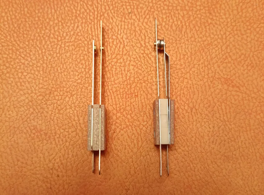
The mechanically switched flipper made two switches do hard electrical work, and the consequences shaped the components used. Both the cabinet button and the EOS switch have to make and break a high, inductive current, and breaking an inductive current draws an arc. That arc pits and erodes the contacts over time, and it is the dominant wear mechanism in these switches. The patent literature describes the situation directly. The arrangement requires the flipper switch and the end-of-stroke switch to break a high-current circuit, with resulting arcing and contact wear, and the high current levels also necessitate a relay to enable or disable the flipper circuits under control of the game logic.
Two design responses follow. First, these high-current switches use tungsten contacts, chosen for their high-current capacity and resistance to wear, in contrast to the gold or silver contacts used on the low-power leaf switches elsewhere in the game (rollovers, targets, and so on) . Tungsten tolerates the arcing and the repeated mechanical hammering far better, though even a tungsten EOS contact eventually pits, thins, and needs filing or replacement, which is among the most routine of all pinball repairs.
Second, where the arc was most severe it was suppressed with a capacitor fitted across the switch contacts, which absorbs the inductive energy at the instant of opening. This is most associated with Williams. As Williams moved into its higher-voltage solid-state flipper circuits, the arcing grew bad enough that the later System 11 games fitted a 2.2 microfarad capacitor across each EOS switch, a measure that carried forward into the WPC games (which also place a small disc capacitor across the cabinet flipper switch) . The combination of tungsten contacts, a suppression capacitor, and a flipper-enable relay is the signature of a circuit in which the switch itself is the power-handling element.
Automatic knock recovery
One property of this arrangement deserves singling out, because it quietly disappears in the eras that follow. Because the EOS switch is mechanically coupled to the flipper’s position, the mechanically switched flipper recovers from a knock entirely on its own. If a fast-moving ball strikes a raised flipper hard enough to drive the bat back down off its stop, the EOS, tracking that movement, changes state and immediately reconfigures the circuit back to full power, driving the flipper up again. No separate logic-level sensor or processor reads the event. The switch is the position feedback, and the recovery is an automatic consequence of the wiring, obtained without any additional circuitry. This point is worth holding onto, because it becomes a recurring theme of the series. Later flipper architectures had to work increasingly hard to recover a behaviour that the mechanically switched flipper produced as a by-product of its own construction.
A mechanical flourish: zipper flippers
Not all flipper innovation of the era concerned the coil. The most striking mechanical elaboration was Bally’s zipper flippers, invented by the designer Ted Zale and introduced on Bazaar in 1966 . In a zipper-flipper game the two bottom flippers are not fixed in place. When the player triggers the right playfield feature, typically a particular mushroom bumper or target, the flippers physically translate toward one another and close the gap between them, narrowing it to less than a ball’s width so that nothing can drain down the centre, while the flippers still flip normally. Hitting a different target reopens them. On Fireball (1972), Zale’s best-known zipper game, a blue mushroom bumper drives the flippers to their inner (closed) position and a yellow one returns them to the outer position .
Mechanically this was driven by dedicated open-flipper and close-flipper relays and a sliding flipper assembly, and it was notoriously sensitive to switch timing and blade adjustment, as anyone who has restored one will attest. Bally produced eighteen zipper-flipper titles between 1966 and 1973 (not counting German-market variants), among them Rockmakers (1968), Four Million B.C. (1971), and Fireball (1972). The feature faded as the three-inch flipper and other design fashions took hold, but it stands as a fine example of how much the era was willing to attempt mechanically, with relays, coils, and switch blades, in order to change how a flipper behaved.
The flipper that stayed mechanical inside the solid-state machine
The natural place to end an account of the electromechanical flipper would be the arrival of the microprocessor, but that is exactly the boundary this series argues is wrong for the flipper. Solid-state pinball arrived in stages. Bally built a microprocessor prototype, Flicker, around the Intel 4004 in 1974 . The first commercially produced solid-state game was Mirco Games’ The Spirit of ‘76 in October 1975 , built on licensed Bally technology and not to be confused with Gottlieb’s similarly named electromechanical title . Bally’s own first solid-state production game, Freedom, followed in December 1976 on a Motorola 6800 board set, and Williams entered with its System 3 board set in 1977, Hot Tip being the usual choice for its first mainstream solid-state game, with Williams converting fully to solid state by December 1977.
What the microprocessor swept away was the relay logic that had run the rest of the game, the steppers, the score motor, and the score reels. It did not, by itself, change how the flipper was driven. In the great majority of early solid-state machines the flipper kept precisely the arrangement described above, a dual-wound coil whose power-to-hold handover was performed by the mechanical EOS switch, the whole flipper circuit typically enabled or disabled as a block by a flipper relay rather than modulated by the processor. The flipper’s high, brief current was still most simply handled by the traditional circuit, and the design was proven, so it was left alone. For a decade or more, the flipper was effectively the last surviving piece of the electromechanical era hiding inside an otherwise solid-state machine. The CPU, in other words, arrived well before the flipper itself became electronically controlled.
That gap is the true subject boundary of this history. Everything around the flipper was now electronic and cheap to reconfigure in firmware, while the flipper remained an island of high-voltage analogue design governed by a switch. Part 2 turns to the first of the two parallel answers the industry found to that problem, namely Data East’s decision to take power off the switch by changing the coil itself.
References
Internet Pinball Database (IPDB), Humpty Dumpty (D. Gottlieb & Co., 1947), machine no. 1254.
Roger Sharpe, Pinball! (E. P. Dutton, 1977), print.
Michael Shalhoub, The Pinball Compendium (Schiffer Publishing), print.
The Strong National Museum of Play, Steve Kordek coin-op and amusements collection.
US Patent 4,384,716 (Powers), Flipper control circuit, 1983, background description of the prior-art dual-wound coil, the end-of-travel switch, and the high-current arcing and relay requirement.
US Patent 4,895,369 (Deger / Data East), Flipper control circuit for pinball machine, 1990, background description of the prior-art series arrangement and its high-current switch wear.
Mission Pinball Framework, Flipper end-of-stroke (EOS) switches.
funwithpinball.com, Flippers, Coils and Power.
flippers.be, Evolution of the flippers on pinball machines.
Bazaar (Bally, 1966); Bally produced eighteen zipper-flipper titles between 1966 and 1973 (excluding German-market variants).
PinWiki, Steve Kordek.
TIME, “Pinball Machine Wizard Steve Kordek Dies at 100,” 24 February 2012.
Marco Specialties, End-of-stroke leaf switch 03-7811 (tungsten contacts for high-current capacity), and associated flipper-circuit arc-suppression capacitor (part 125-5002-00).
homepinballrepair.com, Pinball Switches: Fixing, Adjusting and Cleaning (high-power flipper and EOS contacts are tungsten, arc and require filing or replacement; low-power leaf switches use gold or silver).
Kineticist / This Week in Pinball, The Dawn of the Solid-State Pinball Era.
Wikipedia, The Spirit of ‘76 (pinball).
Pinball Machine Superstore, Summary of Pinball History (Bally Flicker prototype 1974; Williams Hot Tip 1977).
PinWiki, Williams System 3 to 7 (the 2.2 microfarad capacitor across each EOS switch, as fitted on the later System 11 games).
homepinballrepair.com, Rebuild Williams / Bally Flippers (capacitor across the EOS switch and a disc capacitor across the cabinet flipper switch on WPC games).
pinrepair.com, EM Pinball Machine Repair (Genco’s DC solenoid circuits, selenium rectifier characteristics, and failure modes).
Pinside, Triple Action (Genco, 1948).
Internet Pinball Database (IPDB), Triple Action (Williams, 1973), machine no. 2648.
This is Part 1 of a technical history of the pinball flipper. Part 2 covers Data East’s single-wound Deger coil, the first of two parallel answers to taking flipper power off the mechanical switch.