

A Technical History of the Pinball Flipper, Part 2: Data East’s Single-Wound Answer
How Kurt Deger’s single-wound coil changed the flipper circuit, and what Data East’s own service literature reveals about the architecture of the solid-state flipper board.
Introduction
The pinball machine had moved into the solid-state age, but the flipper itself initially behaved mostly as it had in the electromechanical era. Its high coil current still passed through mechanical contacts: the cabinet button and the end-of-stroke, or EOS, switch.
That made the flipper robust and easy to understand, but it also left a hard limit on what the new electronics could do. The switch contacts still arced. The EOS switch still carried real current. The timing of the stroke was still governed by the movement of a leaf switch under the playfield.
Data East attacked that problem in a different way from Williams. Williams, as Part 3 will show, kept the familiar dual-wound coil and changed the way it was controlled. Data East changed the coil itself. This article follows that route: the single-wound flipper coil associated with Kurt Deger, the early circuits that still depended on the EOS switch, and the later solid-state flipper board that moved the flipper into electronics in a much more direct way.
Data East and the single-wound coil
Data East entered the pinball business in 1987 with Laser War . Two years later, beginning with Playboy 35th Anniversary (1989), the company adopted a flipper coil with a single winding in place of the traditional two. The design is credited to Kurt Deger, and became known in the hobby as the Deger design .
The problem was the same one the dual-wound coil had solved decades earlier. A flipper needs a hard initial kick, but it also needs to stay raised without burning the coil. The traditional answer was to use two windings: a low-resistance power winding for the stroke, and a higher-resistance hold winding once the flipper was up.
Data East’s answer was to use one winding and feed it two different voltages. The power stroke used roughly 50 V DC. The hold state used a much lower voltage, often described in repair writing as about 9 V, enough to keep the flipper raised without overheating the coil. The hold supply passed through a diode mounted directly on the coil, a 1N5404 on the early games. Playboy and Monday Night Football carried two diodes on the coil, the second providing rectification, but that refinement was dropped later. The important change was that the low-power hold was no longer a separate winding on the coil. It had become part of the surrounding electrical system.
This was a real change in philosophy. The dual-wound coil built the two operating modes into the coil itself. The Deger design put more of that decision onto the electronics. The coil became simpler; the board, the transformer, and the wiring around the coil became more important.
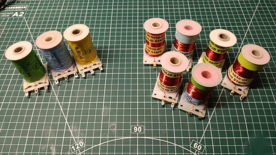
The first version did not, however, remove the EOS switch from the high-power handover. On Playboy 35th Anniversary and Monday Night Football, the normally-closed EOS switch still controlled the change from stroke to hold. The coil received 50 V through the stroke, then the EOS opened at the top and allowed the low-voltage hold circuit to take over. Data East had changed the coil strategy, but not yet the basic fact that a mechanical switch decided when the power stroke ended.
The parallel-coil patent
Deger’s name also appears on a separate Data East patent that is easy to misplace in the story. US Patent 4,790,536, filed in the late 1980s, describes a dual-wound coil with its two windings connected in parallel rather than in the older series arrangement . The EOS switch removes the low-resistance winding at the end of travel, leaving the high-resistance winding to hold the flipper up.
That design belongs here, not in the electromechanical era. It was another Data East attempt to improve the flipper circuit, especially by reducing arcing at the switch. It also shows that Data East did not arrive at the single-wound answer in a straight line. The company was working around the same old problem from more than one direction: how to get a strong power stroke, a safe hold, and less abuse of the EOS contacts.
From EOS handover to timed control
The next question is when the EOS stopped making that decision.
The next step was the dedicated Data East solid-state flipper board, the TY-FFASI. In accounts of that board, the kick-to-hold transition is no longer described as an EOS-controlled event. Instead, the board applies the 50 V power stroke, then drops to the low-voltage hold supply after a fixed interval of about 40 ms, independently of the switch . Robocop is identified as the first full game to use this solid-state flipper board.
This makes best sense as a generational change. The early Deger circuit on Playboy and Monday Night Football still used the EOS switch for the handover. The later board, from Robocop onward, moved that timing into electronics. The exact boundaries should ideally be checked against individual schematics, but the broad movement is clear enough. Data East first changed the coil, then moved the power decision off the switch and onto the board.
That is why Data East is often credited with the first genuinely solid-state flippers. Earlier solid-state games had microprocessors, but many still used relay-gated, mechanically switched flipper circuits. The Data East board was different: it made the flipper itself an electronically controlled mechanism.
Service Bulletin 49: A snapshot of the architecture
Data East’s own Service Bulletin No. 049, issued on 16 November 1993, is one of the best surviving windows into that moment . It is not just a list of fixes. It is Data East explaining to operators and technicians what the new flipper architecture was supposed to be. The title is plain enough: Solid State Flipper - Theory of Operation.
That matters because the board was easy to misunderstand. From the outside, the machine still had a flipper button, a flipper coil, and an EOS switch under the playfield. Those were familiar parts. What had changed was the job each part was doing. SB49 makes the new division of labour clear: each flipper driver contains a one-shot timer, a 50 V driver, and an 8 V driver. The 50 V side gives the flipper its kick. The timer decides how long that kick lasts. The 8 V side holds the flipper up afterwards. The EOS switch is no longer the heavy-current device that changes the coil from power to hold. It has become part of the board’s control logic.
The most interesting detail is the hold supply. Later summaries often call it a 9 V hold supply, which is close enough for casual repair language. Data East’s own document calls it 8 V. More importantly, SB49 shows that this low-voltage supply was not made at the coil and was not simply dropped from the 50 V rail. It came from its own transformer winding as 8 VAC, entered the solid-state flipper board, and was rectified there for the hold circuit.
That is a small detail with a big historical meaning. In the old dual-wound flipper, the distinction between power and hold lived physically inside the coil. There were two windings on the same bobbin, and the EOS switch changed which winding did the work. In the Data East solid-state system, the coil was just one winding. The distinction between power and hold had moved outward into the machine: one supply for the stroke, a separate low-voltage supply for hold, and a board deciding when to use each one.
SB49 even shows how literal that separation was. The 50 V supply enters the board as DC. The hold supply enters separately as 8 VAC, then passes through rectifiers on the flipper board before being used by the hold driver. Data East had not merely replaced a switch with a transistor. It had split the flipper into functions: timing, power stroke, holding supply, and position feedback.
There is also a useful service history point here. The bulletin exists because this architecture created new kinds of confusion. A flipper that fired hard but would not stay up was not necessarily suffering from a bad coil or a dirty EOS contact. It might have lost the low-voltage hold supply. Conversely, a flipper that did not fire at all could point toward the switch path that enabled the 50 V pulse. The old mechanically switched flipper tended to concentrate its trouble around contacts, coils, and adjustment. The Data East board spread the problem across supplies, timing, driver circuitry, and switch inputs.
For a history of the flipper, that is the interesting part. Data East had moved the important question away from the coil and into the system around it. The coil was no longer the whole story. The transformer winding, the rectifier on the board, the one-shot timer, and the switch inputs all became part of what a flipper was.
Foldback: the problem that brought the switch back
Once timing replaced the old EOS power handover, the circuit gained a new weakness. A timer can handle the predictable part of a flipper stroke. It can apply full power for a short period, then drop to hold. What it cannot know is whether a ball has struck the raised flipper and forced it back down.
The mechanically switched flipper handled that automatically. If the flipper was knocked off its stop, the EOS changed state and the power winding came back into the circuit. No software had to notice anything. The switch was part of the power path, so recovery was built in.
Data East had to recreate that behaviour deliberately. From Jurassic Park (1993) onward, Data East games used a normally-closed EOS switch for foldback, a form of knock recovery. SB49 describes the same idea in Data East’s own service language: if the ball knocks the raised flipper back by about 1/16 inch or more, the EOS closes again and the board gives the coil another 50 V pulse.
That is why the switch survived. It was no longer there to carry the main coil current, but the board still needed to know when the flipper had been knocked away from its stop. The timer could manage the normal stroke. It could not predict an impact from the ball.
The EOS had changed jobs. It began as a power-handling contact, became a handover device in the early Deger circuit, then returned as a control input whose job was to catch an event a timer could not see. SB49 is valuable because it catches that transition in Data East’s own words, at the point where the company was explaining the new system to the field.
New components, new failure modes
The single-wound system also brought its own characteristic faults. Because the hold circuit used an SCR, a failed coil diode could cause a distinctive stuck-flipper problem. If the diode no longer clamped the reverse-polarity pulse from the collapsing coil field, that pulse could trigger the holding SCR and leave the flipper energised as if the button were still pressed .
The split architecture also explains the familiar Data East fault patterns. If the low-voltage hold side is weak or missing, the flipper may fire but fail to stay up. If the EOS and cabinet-switch path is not behaving cleanly, the 50 V pulse may not be requested properly. If the hold is too weak and the EOS recloses as the flipper falls, the board can keep giving the coil another power stroke, producing the rapid buzzing action known as a machine-gun flipper.
That failure mode is worth understanding historically, not just as a repair problem. It shows the bargain Data East had made. The old circuit hid a lot of behaviour inside the physical motion of the EOS switch and the two windings of the coil. The new circuit separated those jobs. That made the flipper more electronic, but it also meant the machine now depended on several separate pieces agreeing with one another: the timer, the hold supply, the switch input, and the coil itself.
What the Data East path settled
By the early 1990s, Data East had moved the flipper into the electronic age by changing the coil first and the control circuit second. The single-wound Deger coil replaced the old power-and-hold windings with one winding fed from two supplies. The later solid-state flipper board then moved the timing of the power stroke off the high-current EOS path and into electronics.
Service Bulletin 49 makes that architecture unusually visible. It shows a flipper no longer defined only by a coil and a switch, but by a small control system: a timed 50 V stroke, a separate low-voltage hold supply derived from an 8 VAC transformer winding and rectified on the board, and an EOS input retained for position feedback and foldback. That is a long way from the mechanically switched flipper of Part 1, even though the parts under the playfield still look familiar.
That solved one problem and exposed another. The machine could now time the normal stroke without relying on a high-current mechanical contact. But it still needed to know when the flipper had been knocked down by the ball. The EOS switch survived because it provided something timing could not: real-time information about the position of the flipper.
Williams reached the same destination from the other side. It kept the dual-wound coil, but brought the switching under computer control and turned the EOS into feedback. That system, FlipTronics, is the subject of Part 3.
References
flipperwinkel.nl, Repair DataEast/Sega 1987 to 1995 Pinball Games, Part One (the single-wound Deger design; 50 V kick and low-voltage hold; coil-mounted diodes; “first to use solid-state flippers”).
PinWiki, Data East/Sega (TY-FFASI solid-state flipper board; CPU-timed transition of the order of 40 ms; Robocop as the first solid-state-flipper-board game; normally-closed EOS for foldback from Jurassic Park; early-board EOS-contact defect; the machine-gun failure mode).
Internet Pinball Database (IPDB), Playboy 35th Anniversary (Data East, 1989), machine no. 1822.
Pinside, Data East Left Flipper Sticking (coil-diode failure gating the holding SCR; counter-EMF behaviour).
homepinballrepair.com, Troubleshooting Data East / Sega Pinball Machines (solid-state flipper board low-voltage hold supply; system and game listing including Laser War and Playboy 35th).
US Patent 4,790,536 (Deger / Data East), Parallel coil pinball flipper solenoid, 1988, the parallel dual-wound arrangement, with the EOS removing the low-resistance winding at end of travel.
US Patent 4,895,369 (Deger / Data East), Flipper control circuit for pinball machine, 1990; and US Patent 5,092,597, Solid-state flipper control circuit, primary-source descriptions of solid-state flipper control and the dual-wound prior art it replaced.
Data East Pinball, Service Bulletin No. 049: Solid State Flipper - Theory of Operation, 16 November 1993 (one-shot timer, 50 V driver, and 8 V driver; 8 VAC hold supply entering the solid-state flipper board and being rectified there; 50 V DC power stroke supply; EOS and cabinet switch inputs; EOS adjustment and foldback operation).
This is Part 2 of a technical history of the pinball flipper. Part 3 covers Williams’ FlipTronics system, the dual-wound coil under computer control, and the end-of-stroke switch as feedback.