

A Technical History of the Pinball Flipper, Part 5: Sensing the Flipper Without a Switch
The end-of-stroke switch can be removed from a flipper altogether, and nothing needs to be fitted in its place. The plunger’s position is already present in the coil, encoded in its inductance, and it can be read from the coil’s current whenever the coil is driven.
Introduction
Across this series on the technical history of the pinball flipper, the end-of-stroke (EOS) switch has been asked to do less and less. This final chapter describes Maya Pinball’s patent pending technology, forming the backbone of the Octane platform, that removes the mechanical switch entirely.
An EOS switch exists to report plunger position: its contacts change state according to where the plunger has travelled. What this article sets out is that the coil the plunger moves inside reports that same position, through its magnetic properties, and that the report can be read from the way the coil’s current behaves when it is driven. To see why, it is best to start not with the switch and not with the current, but with the magnetic field the coil produces, which is the part of a flipper every pinball player already has a feel for.
What’s in a name
The Octane name traces mainly to the literature this platform builds on. Reading a solenoid’s own current to learn what its plunger is doing is an established idea in automotive electronics: inductance-based sensing has long tracked an armature’s position within an electromagnetic actuator, most notably in fuel injectors , and the same current-dip-from-motional-back-EMF technique this article builds on is documented for general-purpose DC solenoids in the wider solenoid-driver literature . What is described here is a further application of that same physics, to a mechanism and a fault condition the existing literature was not built to address.
The name also happens to fit neatly: an engine’s octane rating measures its fuel’s resistance to knock, and a flipper struck mid-hold is, in this article’s own vocabulary, a knock too. Fitting, if a little tongue in cheek.
The coil as a store of magnetic energy
A flipper coil is an electromagnet. Drive current through it and it produces a magnetic field, and that field is what pulls the plunger in and throws the bat. This is familiar to anyone who has watched a flipper work from the underside of the playfield. What matters here is where the energy goes. When the coil is driven, energy is stored in that magnetic field, in and around the coil. The field does not appear the instant the voltage is applied, and it does not vanish the instant the voltage is removed. It takes energy to build, and it returns that energy when it collapses. This unwillingness to change quickly is the coil’s defining electrical characteristic.
That characteristic is inductance
Inductance is the measure of how strongly a coil resists a change in the current through it, and it resists that change precisely because altering the current means altering the stored magnetic field, and the field opposes being altered. A coil of high inductance builds and collapses its field reluctantly; a coil of low inductance does so readily.
Inductance is a property the coil possesses at all times, whether or not any current is flowing, in the same way that a flywheel has a moment of inertia whether or not it is turning. It reveals itself only when something attempts to change the current, just as the flywheel’s inertia only makes itself felt when something tries to change its speed. Inductance is the coil’s inertia against changes in current.
A coil's reluctance to change its current cuts both ways. It resists the current building up, and it resists the current collapsing just as hard. The instant a coil is switched off, the field cannot vanish immediately, so the coil keeps driving current in the same direction it was flowing, through whatever path is available. If the only path available is the open switch, the coil forces the current across that gap anyway, as a high-voltage arc, which is exactly the destructive spark that used to burn contacts on unprotected coil switching. In a more modern solid-state driver, this spike can damage the switching transistor.
The fix is a diode wired across the coil, reverse-biased so it does nothing while the coil is driven. The current never reverses; what flips is the coil's role, from load to source:
- Driven: the coil is a load. Current is pushed in, terminal voltage is set by the supply.
- Switch open: the coil is a source. The field forces that same current onward, and to push current out of a terminal rather than absorb it, the terminal polarity has to reverse.
That reversal is exactly the polarity the diode is wired for, off while the coil is a load, on the instant it becomes a source, giving the current somewhere to go: round the coil-diode loop instead of across the open switch. There it decays, dissipated by the coil's own resistance, and is called a freewheeling diode because that is what the current is doing, coasting round the loop until it dies out. Also called a flyback diode, for the spike it suppresses, but freewheeling names the mechanism, not just the symptom.
Reading inductance in the driven current
Inductance of a coil is a property that can be derived by measuring the current flowing through the coil. The voltage across an ideal inductor equals its inductance (L) multiplied by the rate of change of its current (di/dt).
Read plainly, this says that changing the current through a coil quickly requires a large applied voltage, and that for a given applied voltage the current changes at a rate set by the inductance. A high inductance resists the change, so the current builds slowly; a low inductance permits it, so the current builds quickly. This is why, when a flipper coil is first energised, the current does not arrive all at once. The applied voltage has to work against the coil’s inductance, and the current climbs over a short interval rather than appearing instantly. How steeply it climbs is dictated by the inductance. The current, in other words, is where the inductance becomes visible.
Move the sliders to see how voltage, inductance, and the coil’s own winding resistance shape the current rise. The default values for this widget model the real coil measurements shown in the next section. Low values of L allow the current to rise more rapidly.
Inductance depends on where the plunger sits
The inductance of a flipper coil is not a fixed quantity. It is set by the magnetic circuit the coil forms, and the plunger is part of that circuit. The plunger is a slug of iron, and iron carries magnetic field far more readily than air. When the plunger is withdrawn, a long air gap sits in the magnetic path, the field is weaker for a given current, and the inductance is low. As the plunger is drawn in and closes that gap, the path becomes progressively more iron and less air, the field strengthens for the same current, and the inductance rises. The plunger’s position and the coil’s inductance are therefore bound together. Move the plunger and you change the inductance.
An end of stroke (EOS) switch reports plunger position by mechanical contact. The coil encodes the same plunger position in its inductance, by magnetic circuit. The position information is present in the coil properties whether or not a switch is fitted to duplicate it.
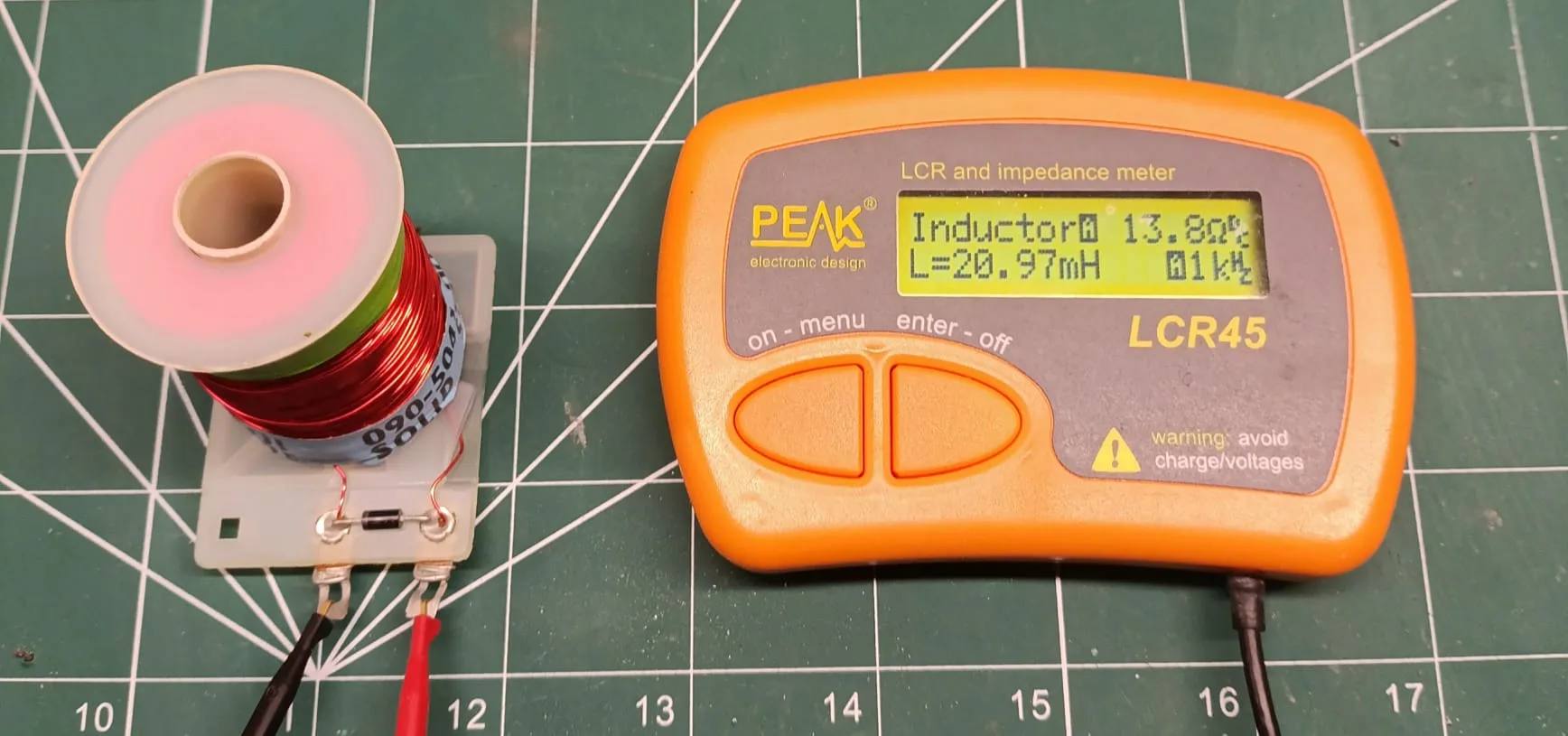
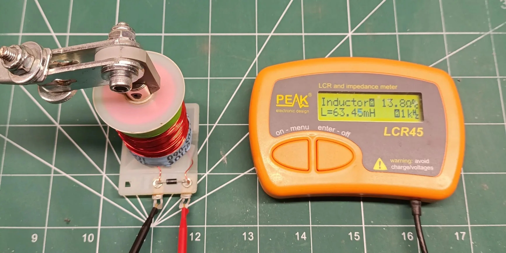
The plunger moves, so the inductance changes
So far the inductance has been treated as one fixed number, which is correct for a coil wound on a core that stays put. A flipper coil is not that. Its plunger moves while the coil is driven, and as established above, a moving plunger is a changing inductance. The relationship has to be extended to account for it. When the inductance itself varies with time, the coil voltage gains a second term:
The first term is the one already discussed, the voltage required to change the current through a fixed inductance. The second term is the new one, and it is the point of the article. It is the current multiplied by the rate of change of inductance, and it is non-zero only while the inductance is changing, which is to say only while the plunger is moving. Hold the plunger still and dL/dt is zero, the second term disappears, and the coil behaves as an ordinary fixed inductor. Set the plunger moving and the term appears, contributing a voltage of its own that either adds to or opposes the driven current, depending on which way the plunger is travelling.
That second term is the plunger’s motion made electrical. It is the mechanism by which the coil reports what its plunger is doing, and everything from here is a matter of reading it.
Note that L in the first term is not a constant either, it is the coil’s instantaneous inductance, set by wherever the plunger currently is. Both terms move with the plunger; the article isolates the second term because it is the one that vanishes when the plunger is still, not because the first term is somehow immune to plunger position.
Seeing the plunger seat
Take the ordinary power stroke, the flip itself. The coil is driven hard, the field builds, and the plunger is pulled from its rest position toward the coil stop. As it travels it is closing the air gap, so the inductance is rising and dL/dt is positive and substantial. Look at what the second term does under these conditions. The rising inductance produces a voltage that opposes the driven current, and that opposition holds the current back. The current, which had been climbing as the field built, is checked while the plunger is in motion. Then the plunger reaches the stop and stops. The inductance stops rising, dL/dt falls to zero, the opposing term vanishes, and the current, no longer held back, resumes its climb.
The result is a distinct feature in the current: a dip, or at the least a pronounced bend, that runs through the stroke and ends at the moment the plunger seats. It is not noise and it is not incidental. It is the direct electrical signature of the plunger moving and then arriving, produced by the second term of the equation above. The coil has reported, in its own current, that the stroke is complete. No switch was consulted. The information came from the magnetic circuit, through the inductance, into the current, exactly as the physics dictates it must.
Move the sliders to see the second term at work. Inductance is fixed here at the two values measured on the coil above, 21 mH withdrawn to 63 mH seated (these coarse fixed values are for demonstration only, as the real inductance value is also affected by the flipper base plate, coil stop, and the plunger is never fully removed in operation). The L term rises gently at first and steeply in the last stretch before it seats (dashed line) since the air gap’s reluctance falls roughly as 1/gap. Seat time is inferred from V and R, a harder-driven coil moves the plunger faster and seats sooner. That late, steep rise in dL/dt is what drives the current down hard just before the seat, not a gentle bend, and the moment it seats, dL/dt drops to zero and the current snaps back to its unimpeded climb. The hatched region is the charge delivered up to the seat; since V is held constant here, multiplying by V gives the electrical energy the supply put into the stroke, printed above the curve. Not all of that becomes motion, some is dissipated in R and some stays stored in the field, so read it as an upper bound on the stroke’s energy, not the plunger’s kinetic energy.
The value of this observation
It is worth pausing on how much has been gained from that one feature, because it is more than it first appears. The end of the power stroke is the moment every flipper control scheme has to identify, because it is when the drive can drop from the full power needed to move the plunger to the modest hold needed to keep it seated. Earlier parts of this series set out the two established ways of finding that moment: a mechanical switch that reports it, or a fixed timer that estimates it in advance and trusts the estimate.
Reading the dip is a third way, and it has a particular virtue. It locates the end of the stroke by observing the event itself, rather than by timing a guess at it or by waiting for a contact to be pushed far enough to close. Because it watches the actual seating, it tracks the mechanism as the mechanism changes. As a coil stop wears and the plunger’s travel lengthens slightly over years of play, a timed estimate drifts out of date, but the observed dip simply moves with the wear. A plunger that fails to seat produces no dip at all, a fault the coil reports plainly and a fixed timer cannot.
The job the EOS switch was kept for
None of this has yet touched the one task the end-of-stroke switch was still doing when this series left it. By the solid-state era the switch had lost the timing role to firmware, and it is worth being clear about why. It lost that role not because timing the stroke had been solved elegantly, but because the switch had proved an unreliable way to do it. Contacts wear, arc, contaminate and drift out of adjustment, and a controller counting off milliseconds is at least consistent. Timing by firmware was the lesser of two imperfect methods, adopted because the switch was poor, not because the underlying need had gone away.
What the switch was kept for, once almost everything else had been handed to firmware, was the single thing a fixed timer genuinely cannot do: catch a raised flipper that has been knocked back down. A ball can strike a held flipper hard enough to drive the plunger off its stop while the coil is still only holding. That event is asynchronous. It arrives whenever the ball happens to arrive, so no schedule anticipates it, and unless it is caught and corrected the flipper collapses and the ball is lost. By this point in the series the switch was no longer carrying coil current itself, as Parts 3 and 4 covered, it was a logic-level signal into the controller, which reopened the instant the plunger moved and told the firmware to re-drive the coil. That signal was its last job, and it is the job that has to be accounted for before the switch can be removed.
An impact is the power stroke in reverse
An impact knocking the plunger away form the end of stroke is the seating dip run backwards. When the ball drives the plunger off its stop, the plunger moves outward, the air gap opens, and the inductance falls. The quantity dL/dt, which was positive as the plunger seated, is now negative, and the second term of the equation changes sign with it. Where the seating dip came from a voltage opposing the current, the knock produces the opposite: a term that aids the current rather than opposing it, as the collapsing field returns its stored energy to the circuit. The current does not dip, it spikes. It is the same coil, the same second term and the same principle, with the sign set by the direction the plunger is moving.
The consequence is that a controller already watching the current for the seating dip can, with no further hardware, use firmware that monitors for ball knock events also. A dip means the plunger has arrived; a spike means it has been driven away. When the spike appears, the controller answers it with a renewed pulse of power that drives the plunger back to its stop. This is the same recovery the EOS switch used to trigger by signalling the firmware to re-drive the coil. However, unlike a switch with a contact gap, the current sensing system is orders of magnitude more sensitive. Far smaller gaps can be detected at far smaller time intervals, allowing the hold current of the flipper to be reduced to almost nothing, while retaining a flipper bat that feels completely rigid when held up. Holding the flipper bat up with reduced current leads to a more energy efficient system that wastes less energy on heating the flipper coil.
The EOS switch’s final task has been absorbed into the more sophisticated driving electronics.
Move the sliders to see why a knock only sometimes registers. This is a real mechanical simulation, not a scripted bump: the ball’s contact is a fixed-length push, a few milliseconds, that ramps up and fades like any impact, and the force slider only sets how hard that push gets at its peak. It has to work against a magnetic hold that scales with the square of the hold current, dashed line. Below that hold, the push never wins and the current stays flat at the hold current. Above it, the push crosses the hold partway through its ramp, so a harder knock crosses it earlier in the same fixed contact window, not because the contact itself starts sooner, and from that earlier start the plunger is pushed off its seat and the current shows a bigger, faster hump. This simulation shows the passive response of the coil. In a real closed-loop Octane system, the controller delivers a huge power pulse to keep the flipper rigid microseconds after the onset of a disturbance.
What the switch was costing
Taking the switch out, then, costs nothing in capability, and several things are gained in return. Reading the coil’s own current takes a genuinely capable analogue front end, current sensing fast and clean enough to catch a dip or a spike in microseconds. That is not a trivial thing to design. But it is a cost paid once, in a board that already exists to drive the coil, not a cost paid again on every unit built. A mechanical part cannot make that trade: it has to be stamped, stocked, assembled by hand, wired, and adjusted, on every single unit, and every one of those steps is a place to get it wrong. The point of the electronics is to let the mechanism underneath it get as simple and dumb as possible.
Bally baseplates were, at at one point in time, drilled symmetrically so the same plate could sit on either side of the cabinet. That never removed the handedness, because the switch still had to go somewhere on it. Its bracket, its actuator, and its fasteners were handed hardware, so the parts list still carried a left-hand and a right-hand kit even when the plate itself did not need one. With the switch gone entirely, there is nothing left on the assembly that cares which side of the cabinet it is going on. The baseplate can be a single flat, symmetric, sheet-formed part. One simple SKU.
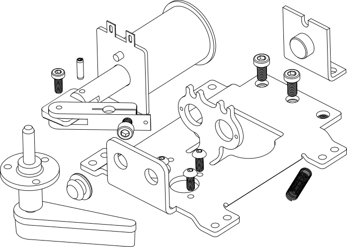
The new MAYA Octane baseplate uses identical hole spacing for mounting the mech to the playfield as 90s Bally/Williams flipper mechs. This is the flipper mech design used by most boutique manufacturers today. A machine fitted with this platform can be serviced with an OEM unit, or, in a pinch, with a period Bally/Williams mechanism with its EOS switch and wiring simply cut away and left disconnected. Backward compatibility of this kind falls out of keeping to an established mounting pattern, while simultaneously simplifying the mech.
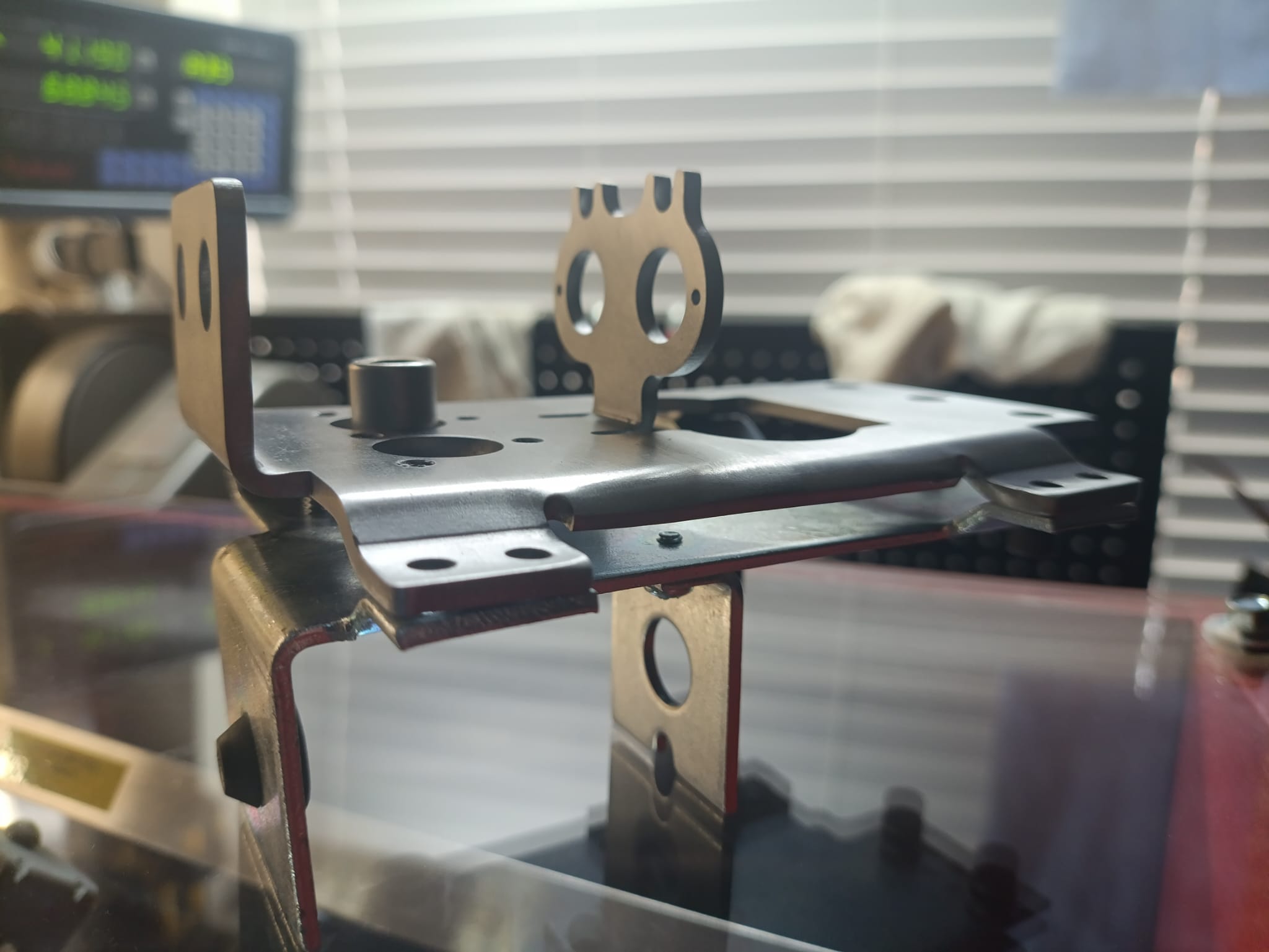
With the switch removed, there is no contact under the playfield left to foul, arc, or drift out of adjustment. There is no wire run from the switch to the driver board, so nothing has to be routed or terminated. The controller gets flipper diagnostics for free: a plunger that seats slowly, fails to seat, or comes back with a dirty baseline shows up as a fault in that same signal allowing for more rapid and precise fault finding.
There is a modest electrical benefit as well. The controller can act on the spike immediately rather than waiting for a switch to trip, the hold current no longer needs the margin that used to cover for the switch’s own slack, so the coil runs a little cooler and a little more efficiently while a flipper is held up. That is real, but it is not the main event. It is a side effect of removing one blunt sensor, not a redesign of how the coil is driven. The larger gain from watching the current this closely is what it makes possible for the drive itself, which is the subject of Part 6.
What the coil already knew
The end-of-stroke switch has done less and less work over the years. It used to carry the full coil current and decide, by mechanical contact, when the stroke was over. Firmware took that decision away from it once coils were switched by timed pulses instead, and the switch was left with one task that seemed to genuinely need it: catching a knock. It doesn’t need it either. The plunger’s position was in the coil’s inductance the whole time, and the inductance was in the coil’s current the whole time. The EOS switch is gone, and nothing was lost, because the coil was already saying all of it.
References
Siemens Automotive Corporation, US Patent 6,657,847, Method of using inductance for determining the position of an armature in an electromagnetic solenoid (dynamically estimating armature position from real-time solenoid inductance, developed for actuators including fuel injectors).
Manu Balakrishnan and Navaneeth Kumar N, Texas Instruments, Detection of Plunger Movement in DC Solenoids (June 2015) (derives the same two-term solenoid voltage equation used in this article, and detects plunger movement from the resulting dip in coil current caused by motional back-EMF).
This is Part 5 of a technical history of the pinball flipper. Part 6 takes up what that same reading makes possible once the switch is gone: shaping the flip itself, in software.