
Pinball Coil Chart: Measured Resistance and Inductance Data
By Nick C, engineer and founder of MAYA Pinball. Last updated 22 September 2026.
Resistance is the figure every coil chart publishes. It sets how much current eventually flows and how rapidly the coil gets hot. It says nothing about how quickly that current arrives, or how hard the coil pulls once it does. Pinball coils fire in pulses of tens of milliseconds, so how quickly matters. That is what inductance adds, and it is rarely published for pinball coils.
- Two coils measuring the same resistance can differ by up to 23 % in ampere-turns (24-900 vs 23-1100). Resistance is the number everyone quotes, and on its own it doesn't tell you how hard a coil hits.
- The strongest coil here dissipates over a kilowatt. 21.7 A at 48 V, which is why coils are pulsed and never left on.
- A coil pulse is about 95 % heat. A 30 ms pulse into an AE-23-800 draws up to 18 J from the supply, and at most 0.85 J of that moves the plunger.
- Some coils don't have published winding specs. Two were estimated here without unwinding a coil, by measuring inductance.
This is a set of bench measurements covering 24 pinball coil types. Five of those types were measured twice, as duplicates were to hand, giving 29 coils in total. The set covers standard playfield coils, small SM1 magnet coils, and single and dual-wound flipper coils. These are the coils that were readily available, and more will be added over time.
Each winding was measured for DC resistance (4-wire), inductance with the bore empty and with a flipper armature inserted, winding diameter, bobbin length and mass. Dual-wound coils were measured one winding at a time, so there are 33 windings in all. Every numerical value in this document was measured in-house at MAYA Pinball. Derived values such as wire length, current, ampere-turns and time constant are calculated from those measurements.
What each measurement shows
- Resistance sets the steady-state current at a given voltage, and with it the power dissipated in the winding (V²/R: about 610 W for an AE-23-800 at 48 V). It is measured 4-wire because at 3 to 4 Ω a typical pair of probe leads adds 0.1 to 0.2 Ω. That is several percent, more than the 1 % spread between samples of the same coil.
- Inductance with the armature in is the closest bench equivalent to the coil at work, with iron in the bore. It sets how fast the current rises in service (τ = L/R, a few milliseconds) and how much energy the field stores, which has to circulate round the freewheeling diode loop at switch-off. It also identifies the winding. The iron dominates, so inductance divided by turns squared comes out at about 24.5 nH/turn² for every playfield coil, whatever the gauge. That makes it possible to check a turns claim, spot a rewound coil, or recover an unpublished spec.
- Air-core inductance is the winding on its own. It depends on the shape of the winding as well as the turns, so it varies more from coil to coil.
- The difference between the two is what matters for force. A coil pulls because its inductance changes as the plunger moves in, not because its inductance is high. A coil whose inductance barely rises when iron enters barely pulls. The two readings bracket the stroke, and give the energy estimate further down the page. The same change also shows up in the coil current as the plunger moves, which is how a controller can sense plunger position with no end-of-stroke switch.
All of this assumes the conventional open-loop drive: a fixed voltage for a fixed time, with the coil’s own resistance and inductance deciding what current flows. Under closed-loop current regulation, as on MAYA’s Octane platform, much of it stops mattering. The controller holds a target current, so resistance, and the way it drifts as a coil heats, drops out as long as the coil and supply can still reach the target. That is why a coil built for regulation is deliberately over-specified: it needs headroom, and the feel of the flip comes from the target the controller follows rather than from the winding. What remains of the coil’s own character is turns, since ampere-turns are then simply the target current times the turns, and inductance, which still limits how quickly any controller can get the current there.
These measurements were enough to recover winding specs for flipper coils where none has been published, or where the published figure doesn’t fit the coil (see estimated specs).
The data
Coils are grouped by type. Where two samples of the same coil were measured, both are listed (#1 and #2). “Williams label” marks a coil with explicit Williams branding.
Columns
- Spec is gauge and turns as printed on the label. The notation “pub” marks a spec published by a supplier but not printed on the coil, and “est” (≈) a spec estimated from these measurements (see estimated specs).
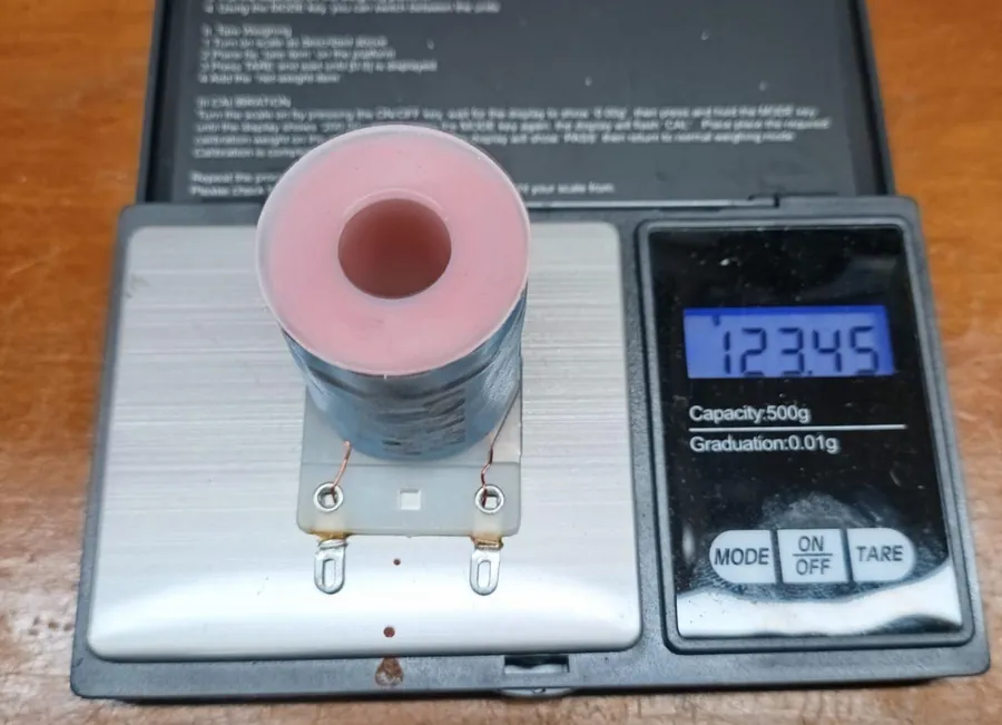
- Mass is the whole coil, including bobbin, lugs and diode. Treat it as a relative guide only. Coils removed from machines can carry solder residue on the lugs, which is enough to shift the figure, so the 0.01 g the scale displays overstates the real precision.
- Winding OD is the outside diameter of the winding, measured at its widest point. It includes any paper wrap or label, and some windings don’t fill the full length of the bobbin, so treat it as a reference figure rather than a precise dimension. On dual-wound coils the power winding sits inside the hold winding, and each has its own OD.
- R is DC resistance, measured 4-wire at 20 °C (68 °F).
- L air is inductance with the bore empty, and L armature with a flipper armature pushed fully in.
Every row can be linked to directly, for example #ae-26-1500 or #fl-11629.
What resistance should a pinball coil be?
It depends on the gauge and turns, not on whether the coil is good or bad. Across this set it runs from 2.2 Ω for a 22-600 up to 275 Ω for the fine 34 AWG hold winding of a linear flipper coil, so compare a coil against the same model in the tables below. All resistances are 4-wire at 20 °C, and a warm coil reads high (see methodology).
Which pinball coil is the strongest?
Ampere-turns at 48 V is the fairest single comparison. In this set the 090-5023-OT (22-600) leads at 13,020 ampere-turns, drawing 21.7 A and dissipating 1,042 W, which is why a coil like this is only ever pulsed. Lower resistance helps, but only up to a point: see Does a lower resistance pinball coil hit harder?
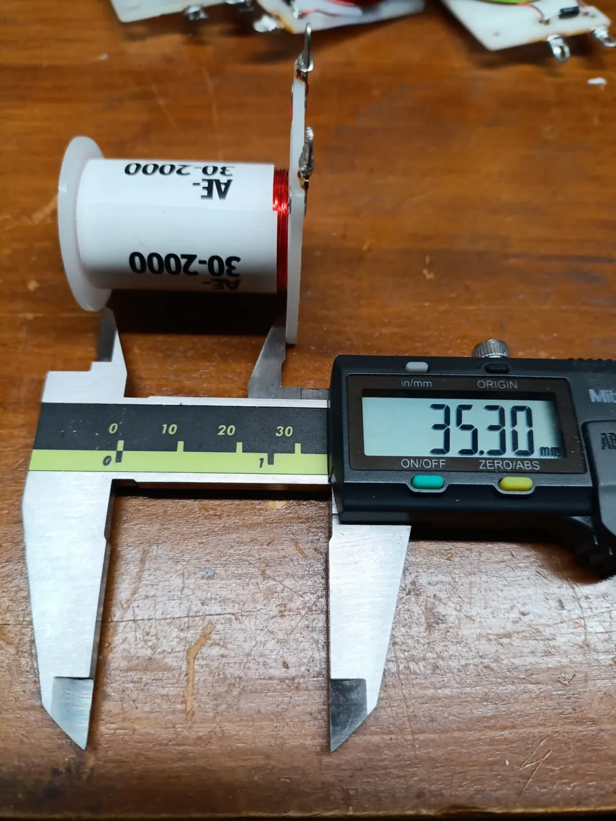
Playfield coils, 35.3 mm (1.39 in) bobbin
Derived values at 48 V
The measured values describe the coil on the bench. The derived values turn them into what the coil does in a machine, at 48 V, a typical modern flipper and coil supply. They assume a cold coil and a perfect supply with no wiring losses.
- Wire length = R / (Ω/m for the gauge). How much copper is in the coil, and the figure you’d need to rewind one.
- Max current = V/R. The current a fixed-voltage pulse heads towards but never exceeds, and what the fuse, driver transistor and wiring have to carry.
- Ampere-turns = current × turns. What sets how hard the coil pulls, and the fairest single number for comparing coil strength.
- Power = V²/R. How fast the coil turns electricity into heat at full current, and why coils are only ever pulsed at this voltage, never left on.
- τ = L armature / R, 1.0 to 5.4 ms across the set. The electrical time constant with the armature held fully in, as if the iron were fixed in the core. It is purely a comparison value. In a real flip the armature moves, the inductance climbs from the air-core value towards the seated one, and the moving iron pulls the current down as it goes, a dynamic system that would need a much more complex model to describe. The bench values also leave out the mech: the bracket and coil stop raise the inductance, so installed time constants will be longer.
- Armature/Air L is the inductance ratio, explained below.
- AL = L armature / turns², the inductance per turn², explained below.
- Stroke energy limit = ½ I² ΔL. The most mechanical work the coil could do in one stroke at full current, explained under energy per stroke.
| Coil | Wire length | Max current (A) | Ampere-turns | Power (W) | τ (ms) | Armature/Air L | AL (nH/turn²) | Stroke energy limit (J) |
|---|---|---|---|---|---|---|---|---|
| AE-26-1500 (#1) | 103 m 339 ft | 3.5 | 5,211 | 167 | 3.96 | 3.08 | 24.3 | 0.22 |
| AE-26-1500 (#2) | 104 m 340 ft | 3.5 | 5,195 | 166 | 3.96 | 3.09 | 24.4 | 0.22 |
| AE-26-1400 | 96 m 316 ft | 3.7 | 5,212 | 179 | 3.76 | 3.21 | 24.7 | 0.23 |
| AE-26-1200 | 78 m 255 ft | 4.6 | 5,541 | 222 | 3.37 | 3.48 | 24.3 | 0.27 |
| AE-26-1200 (Williams label) | 78 m 254 ft | 4.6 | 5,550 | 222 | 3.29 | 3.39 | 23.7 | 0.26 |
| 090-5044-OT (#1) | 79 m 258 ft | 4.6 | 5,464 | 219 | 3.40 | 3.35 | 24.9 | 0.26 |
| 090-5044-OT (#2) | 79 m 260 ft | 4.5 | 5,435 | 217 | 3.32 | 3.40 | 24.5 | 0.25 |
| AE-25-1000 | 66 m 217 ft | 6.8 | 6,849 | 329 | 3.47 | 3.27 | 24.3 | 0.40 |
| AE-30-2000 | 114 m 373 ft | 1.2 | 2,494 | 60 | 2.54 | 3.85 | 24.4 | 0.056 |
| AE-27-1200 | 72 m 237 ft | 3.9 | 4,719 | 189 | 2.91 | 3.65 | 24.6 | 0.20 |
| 090-5004-OT | 95 m 312 ft | 3.0 | 4,490 | 144 | 3.45 | 3.42 | 24.6 | 0.18 |
| AE-24-900 (Williams label) | 61 m 201 ft | 9.3 | 8,379 | 447 | 3.92 | 3.20 | 25.0 | 0.60 |
| AE-24-900 | 61 m 199 ft | 9.4 | 8,454 | 451 | 4.07 | 3.26 | 25.7 | 0.64 |
| 090-5023-OT | 42 m 137 ft | 21.7 | 13,020 | 1,042 | 3.98 | 3.07 | 24.5 | 1.40 |
| AE-23-800 | 56 m 185 ft | 12.7 | 10,188 | 611 | 4.18 | 3.00 | 24.6 | 0.85 |
| 090-5001-OT | 57 m 186 ft | 12.7 | 10,129 | 608 | 4.18 | 3.06 | 24.8 | 0.85 |
| 090-5001-ND | 56 m 184 ft | 12.8 | 10,267 | 616 | 4.26 | 3.13 | 24.9 | 0.89 |
Small SM1 coils, ~17 mm (0.67 in) bobbin
Derived values at 48 V
| Coil | Wire length | Max current (A) | Ampere-turns | Power (W) | τ (ms) | Armature/Air L | AL (nH/turn²) | Stroke energy limit (J) |
|---|---|---|---|---|---|---|---|---|
| SM1-26-600 | 33 m 109 ft | 10.8 | 6,460 | 517 | 1.95 | n/a | 24.1 | n/a |
| SM1-26-600 (Williams label) | 34 m 110 ft | 10.7 | 6,394 | 512 | 1.86 | n/a | 23.3 | n/a |
Single-wound flipper coils, 49.5 mm (1.95 in) bobbin
Derived values at 48 V
| Coil | Wire length | Max current (A) | Ampere-turns | Power (W) | τ (ms) | Armature/Air L | AL (nH/turn²) | Stroke energy limit (J) |
|---|---|---|---|---|---|---|---|---|
| 090-5030-OT | 77 m 252 ft | 9.4 | 10,292 | 449 | 4.68 | 3.13 | 19.9 | 0.72 |
| 090-5025-OT | 116 m 381 ft | 4.9 | 7,706 | 236 | 5.06 | 2.99 | 20.1 | 0.40 |
| 090-5020-20T | 64 m 211 ft | 14.1 | 12,672 | 676 | 4.64 | 2.95 | 19.5 | 1.04 |
| 090-5020-30 | 60 m 196 ft | 12.0 | 10,832 | 578 | 3.97 | 3.28 | 19.6 | 0.80 |
| 090-5041-OT | 129 m 424 ft | 3.5 | 6,299 | 168 | 4.63 | 3.03 | 19.6 | 0.26 |
| 090-5032-00 | 83 m 272 ft | 10.9 | 11,814 | 525 | 5.42 | 2.84 | 20.4 | 0.92 |
Dual-wound flipper coils
Derived values at 48 V
| Coil | Wire length | Max current (A) | Ampere-turns | Power (W) | τ (ms) | Armature/Air L | AL (nH/turn²) | Stroke energy limit (J) |
|---|---|---|---|---|---|---|---|---|
| FL-11629 power | 60 m 197 ft | 12.0 | 9,567 | 574 | 3.95 | 3.32 | 24.8 | 0.79 |
| FL-11629 hold | 236 m 774 ft | 0.4 | 1,135 | 18 | 1.76 | 1.81 | 24.9 | 0.0072 |
| FL-11753-1 power | ≈ 72 m 237 ft | 5.0 | ≈ 4,963 | 238 | 2.61 | 3.46 | 25.3 | 0.22 |
| FL-11753-1 hold | ≈ 284 m 932 ft | 0.3 | ≈ 1,193 | 15 | 2.36 | 2.12 | 25.0 | 0.0094 |
| 090-5083-03-ND power | ≈ 60 m 195 ft | 7.6 | ≈ 6,837 | 365 | 3.09 | 3.81 | 24.1 | 0.42 |
| 090-5083-03-ND hold | ≈ 255 m 836 ft | 0.3 | ≈ 1,242 | 17 | 2.29 | 2.14 | 25.0 | 0.010 |
| A-24570/34-3600 power | 34 m 112 ft | 16.7 | 9,497 | 800 | 2.64 | 3.37 | 23.4 | 0.74 |
| A-24570/34-3600 hold | 321 m 1054 ft | 0.2 | 628 | 8 | 1.01 | 1.53 | 21.5 | 0.0015 |
Inductance: the AL rule
Measure a coil’s inductance with the armature in, and you can count its turns without unwinding it. Theory says that for a given coil shape, inductance scales with the square of the turns, so every coil of the same class should land on one straight line. The plot below is a check of the measurements against that model. Coils from different manufacturers, wound with anything from 22 to 32 AWG wire, agree with it to within about 4 %. That agreement is what justifies using the line to recover the unpublished specs further down, and it’s why a coil that falls off the line deserves suspicion.
AL, the inductance factor, is a coil’s inductance divided by its turns squared. It is the same figure transformer and ferrite core datasheets quote, usually in nH/turn². It depends on the shape of the coil and what’s in the core, but not on the wire gauge or number of turns, so coils built on the same bobbin should share the same AL.
The data bears this out within each class of coil. With a flipper armature inserted, the 35.3 mm (1.39 in) playfield coils come out between 23.7 and 25.7 nH/turn², from 23-800 all the way to 30-2000. The small SM1 coils give 23.3 and 24.1. Both windings of the Williams FL-11629 flipper coil give 24.8 and 24.9. It is the only WPC flipper coil in this set with a full published spec that fits the coil. The flippers.com chart also lists FL-11630 as 23-600/30-2600 and FL-11722 as 24-600/30-2600, but the Pinball Medic chart gives those as the specs of their series-wound equivalents, and they don’t fit the WPC coils’ resistance. A 30 AWG hold of 2,600 turns at the published 160 to 161 Ω would need a mean turn about 58 mm across, on a flipper coil whose hold winding is about 35 mm across at its widest. The same problem with the FL-11753 hold is covered under estimated specs.
The Stern single-wound flipper coils are a different class of coil. They are flipper coils, not playfield coils, and they have their own table above. They sit on a 49.5 mm (1.95 in) bobbin, and they come out consistently lower, at 19.5 to 20.4 nH/turn², with lower air-core values too. The cause has not been established. Bobbin length on its own doesn’t explain it, because the Williams FL-11629 is also on a 49.5 mm bobbin and sits with the playfield coils at 24.8. The bore, sleeve and armature are the same across these coils. The one construction difference that could account for it is how the winding fills the bobbin, for example a winding that stops short of the flanges or finishes on a part-filled layer. This has not been checked. The AL figure for one class should not be applied to the other.
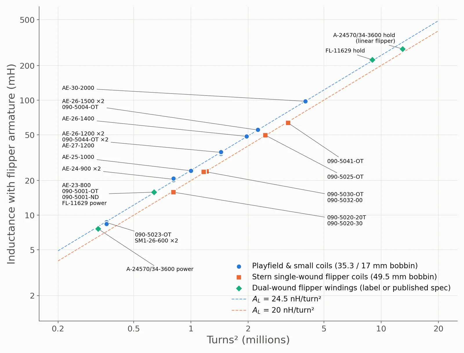
The A-24570/34-3600 linear flipper is on a shorter 34.6 mm bobbin and is a different design. Its power winding sits on the line at 23.4 nH/turn², and its hold a little below, at 21.5.
How do you work out a coil’s turns without unwinding it?
Measure the inductance with a flipper armature fully in, divide by the AL for that class of coil, and take the square root: N = √(L armature / AL). A playfield coil reading 35 mH, for example, works out at √(35 mH / 24.5 nH) ≈ 1,200 turns. Expect about ±5 %, and treat a coil that lands well off its line as suspect.
Inductance ratio, armature in to air core
This ratio says how much of a coil’s magnetic field actually works through the armature. The pull on the armature comes from the inductance changing as it moves in (F = ½ I² dL/dx), so the useful quantity is how much inductance the armature adds: the armature-in reading minus the air-core reading, ΔL. For an AE-26-1500 that’s 54.69 − 17.77 = 36.9 mH. At a ratio of 3, two-thirds of the armature-in inductance is created by the armature. At 1.5, only a third is. The rest is field in the air around the winding, which has to be built up on every pulse and dumped through the freewheeling diode at switch-off, but never pulls on anything.
A high ratio is useful for three reasons:
- More work per stroke. The stroke energy limit scales directly with the gain in inductance.
- Less wasted field. Less of the energy put into the coil goes into field that does nothing.
- A clearer position signal. A bigger change in inductance gives a bigger feature in the coil current as the armature moves, the signal a controller uses to sense plunger position without a switch.
The ratio on its own doesn’t give the pull. That also depends on the size of the gain, the current, and how the change is spread along the stroke. Most of it happens in the last few millimetres, as the air gap closes.
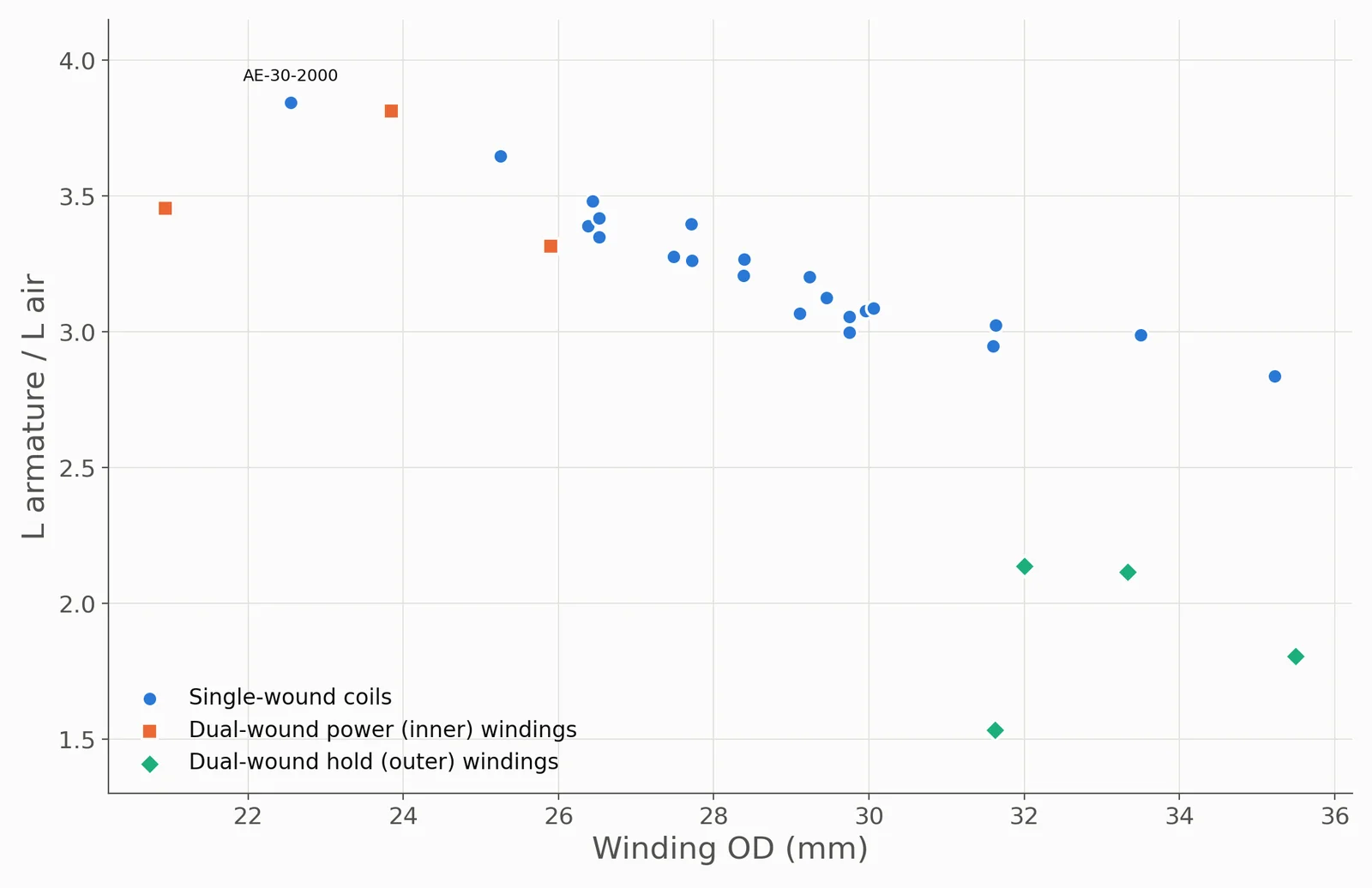
For single-wound coils the ratio runs from 2.8 to 3.9, and it follows the winding OD rather than the number of turns. In a slimmer winding more of the field sits inside the bore, where the armature can use it. AE-30-2000, the slimmest here at 22.55 mm (0.89 in), has the highest ratio (3.85).
The hold windings on dual-wound flipper coils only reach 1.5 to 2.1. They are wound over the top of the power winding, so much of their field sits in air the armature never reaches. That suits the job, and it’s why dual-wound flipper coils have always been built this way round. The power winding, which has to throw the armature across the stroke, gets the prime position right next to the bore. The hold winding only has to keep a seated armature in place, where the air gap is almost closed, so it can sit on the outside.
Flipper armature or steel rod
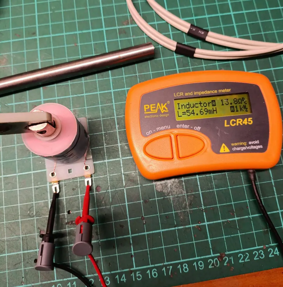
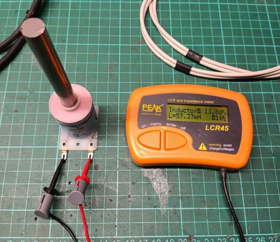
Both a flipper armature and a 10 cm (4 in) bright steel rod were tried in the same AE-26-1500 (sample #1, shown below). With the bore empty it reads 17.77 mH. The armature takes that to 54.69 mH, 3.08 times the air-core value, and the rod to 57.37 mH, 3.23 times. The rod reads only 4.9 % higher than the armature, even though the rod is a far bigger piece of steel with most of its length sticking out of the coil. What counts is the iron inside the bore. Steel outside the coil adds comparatively little. All inductance values here were taken with a flipper armature, as it’s a standard part anyone can repeat the measurement with.
Installed in a machine, the rest of the mechanism joins in. The coil bracket, coil stop and linkage, and the materials they are made of, all form part of the magnetic path and change the inductance. The figures here are for the bare coil on the bench: a consistent reference, not the inductance the coil will have in a working mech.
Unpublished flipper coil specs, estimated
Williams WPC flipper coils use part numbers such as FL-11753-1. Unlike a playfield coil label such as AE-23-800, the number says nothing about gauge or turns, and suppliers generally only publish resistances. The flippers.com master coil chart is the most complete public listing. It gives FL-11629 in full, as 23-800/32-3000. For FL-11753 it lists the power winding as unknown (”?”) and the hold as 30-2600, and the Pinball Medic coil chart shows the same entry. Neither chart lists the Stern 090-5083-03-ND at all, and no winding spec for it turned up on supplier pages or forums.
That gives a reference to calibrate against. Both FL-11629 windings measure 24.8 nH/turn² with the armature in. From there, turns for the other coils follow from their inductance, and gauge follows from their resistance.
| Coil | Power | Hold | Chart listing | Published R, power / hold (Ω) | Measured R, power / hold (Ω) |
|---|---|---|---|---|---|
| FL-11629 (strongest) | 23-800 pub | 32-3000 pub | 23-800/32-3000 | 4.0 / 132 to 133 | 4.01 / 126.9 |
| FL-11753-1 (weakest) | ≈ 26-1000 | ≈ 32-3800 | ?/30-2600 | 9.8 / 165 | 9.67 / 152.9 |
| 090-5083-03-ND (Stern) | ≈ 25-900 | ≈ 32-3550 | not listed | n/a | 6.32 / 137.2 |
How many turns does an FL-11753-1 have?
No complete winding spec is published. The flippers.com chart lists the power winding as unknown and the hold as 30-2600, which doesn’t fit the coil (see below). From its inductance and resistance it is estimated here at about 26-1000 power and 32-3800 hold, with turns good to about ±5 %. The method is set out directly below.
Method
- Turns: N = √(L armature / AL), using AL = 24.8 nH/turn² from FL-11629, rounded to the nearest 50.
- Gauge: resistance divided by an estimated wire length (turns × mean turn length). The mean turn length is scaled from FL-11629 using each winding’s inner and outer winding diameter, and the result is rounded to the nearest standard AWG.
- Hold wire: measured at 0.22 to 0.24 mm (0.0087 to 0.0094 in) over the enamel on every dual-wound coil. That matches 32 AWG (0.202 mm bare) and rules out 31 AWG (about 0.25 mm enamelled) and 33 AWG (about 0.20 mm). Both estimated hold windings come out at 32 AWG independently, matching the published FL-11629 hold.
Uncertainty
Turns should be good to about ±5 %. Gauge is the nearest standard size rather than a measurement, and the FL-11753-1 power winding falls between 26 and 27 AWG depending on how the mean turn length is modelled (26 is given here). None of the estimates has been checked by unwinding a coil. They are consistent with each other, though: as the coils get weaker, the power winding uses finer wire and more turns, and its winding OD shrinks to match.
Published power winding resistances are within about 1.5 % of the measured values. Measured holds come in 4 to 7 % under the published figures, well within the spread owners report (FL-11630 holds, for example, are reported anywhere from 132 to 160 Ω).
The listed FL-11753 hold spec
The 30-2600 hold listed for FL-11753 doesn’t fit the coil. The hold wire measures 0.22 to 0.24 mm over the enamel, and 30 AWG is 0.255 mm before enamel is added. The resistance rules it out too: 2,600 turns of 30 AWG at the measured 152.9 Ω would need about 450 m of wire, a mean turn about 55 mm across, on a winding only 33 mm across at its widest. The same chart lists FL-11630 as 23-600/30-2600, which Pinball Medic describes as the series-wound equivalent of FL-11630. The FL-11753 hold figure looks like the same kind of equivalent carried over, rather than the actual winding.
Energy per stroke: an upper bound
The inductance measurements put a ceiling on how much mechanical energy a coil can deliver in one stroke. If the current were held at I while the armature moved from fully out to fully in, the work done by the field could be no more than
This is the stroke energy limit given in the tables. At 48 V it comes to about 0.01 J for the hold windings, 0.2 to 0.3 J for the 26 AWG playfield coils, and up to 1.40 J for the 090-5023-OT (22-600). For comparison, a 30 ms pulse at 48 V into an AE-23-800 draws about 18 J from the supply, and an 80 g pinball at 4 m/s (9 mph) carries 0.64 J. Almost all of the electrical energy ends up as heat in the winding.
½I²ΔL is the change in magnetic co-energy between the two end positions at constant current. A real stroke delivers less, for three reasons:
- Small-signal inductance. The LCR meter measures at 1 kHz with a tiny current. At the several amps of a real pulse the iron starts to saturate, and the armature-in inductance drops.
- Back-EMF. The moving armature generates a voltage that pulls the current down during the stroke. It's the same effect a controller can use to detect the plunger seating.
- Travel. In a real mechanism the armature never starts fully withdrawn, and the coil stop and linkage limit its travel.
Treat it as a way to compare coils, not a prediction of ball speed.
Methodology
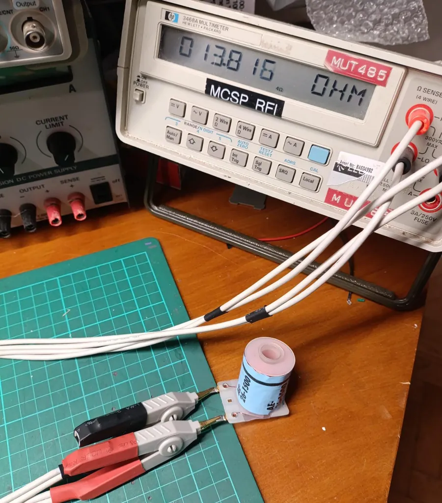
Resistance. Hewlett-Packard 3468A bench multimeter in 4-wire mode, with Kelvin clips on the coil lugs. One pair of leads carries the test current and a separate pair senses the voltage right at the lugs, so the resistance of the leads and clip contacts drops out of the reading. This matters at low ohms. On a 3 to 4 Ω flipper power winding, 0.1 to 0.2 Ω of lead and contact resistance is several percent, more than the difference between two samples of the same coil. The resistance an LCR meter shows alongside its inductance reading is no substitute. The Peak LCR45 reports the AE-26-1500 as 13.8 Ω, measured through two clip leads and displayed to 0.1 Ω, against 13.816 Ω on the 4-wire meter. That’s fine as a sanity check on a high-resistance coil, but too coarse for a 4 Ω winding. On dual-wound coils each winding was measured on its own pair of lugs (right to middle, and middle to left).
Inductance. Peak LCR45 LCR meter, with every reading taken at 1 kHz. Each winding was measured twice, once with the bore empty and once with a standard flipper armature pushed fully in. The SM1 coils were only measured with the armature in. Note that the LCR45 picks its test frequency automatically and can switch to 15 kHz on low-inductance coils, where armature-in readings come out far too low, so check the frequency it reports.
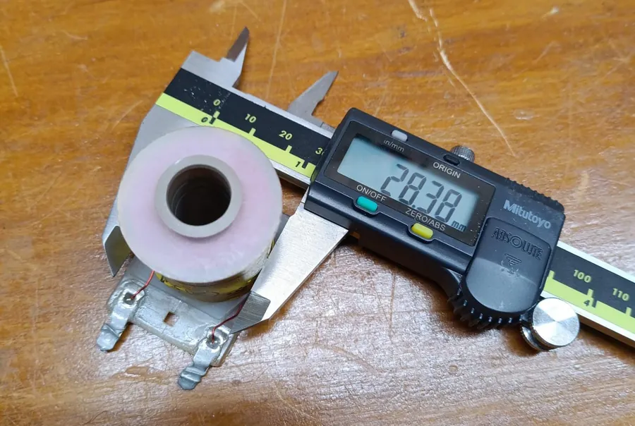
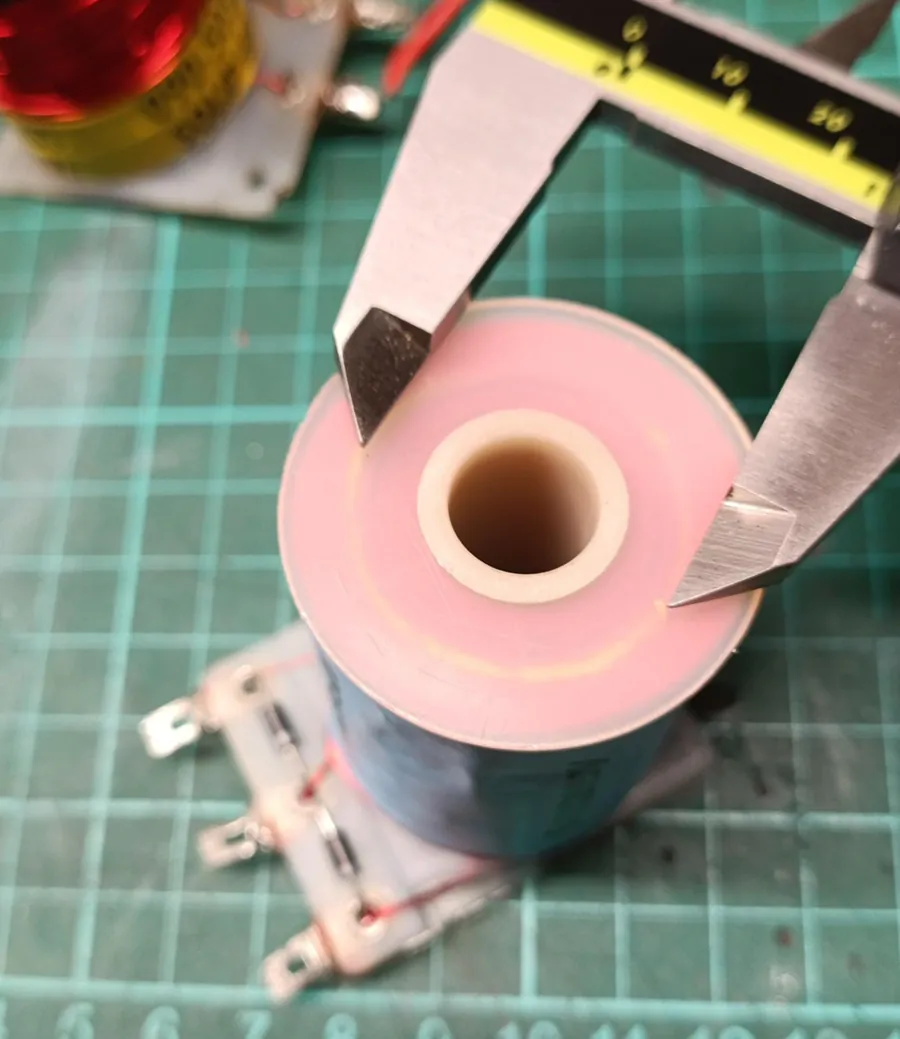
Dimensions. Mitutoyo digital caliper. Bobbin length is measured between the flanges, and is the length available to the winding. Winding OD is measured across the widest point of the winding, including any paper wrap. Where a winding doesn’t fill the full length of the bobbin, the widest point was still used, to give a consistent reference. On dual-wound coils the outer (hold) OD is a caliper reading. The inner (power) OD was read from the top of the coil under bright light, where the edge of the power winding shows through the flange, so it is less precise.
Mass. Whole coil on a 0.01 g resolution scale.
Conditions. All measurements were taken cold, at 20 °C (68 °F) ambient. Copper resistance rises by about 0.4 % per °C, so a warm coil will read high.
Repeatability. Where two samples of the same model were measured, they agree to within 1.1 % on resistance and 3.4 % on inductance with the armature in.
- Copper resistivity 1.724 × 10⁻⁸ Ω·m at 20 °C.
- Bare wire diameter d = 0.127 mm × 92^((36 − AWG)/39). Wire length = R / (Ω/m for the coil's gauge).
- Current, ampere-turns and power at 48 V are steady-state values, V/R, with no supply or wiring resistance.
- τ = L armature / R. AL = L armature / turns².
- ½I²ΔL uses the steady 48 V current and the small-signal inductances. It is an upper bound (see above).
- Rows marked ≈ inherit the ±5 % uncertainty in estimated turns.
How to cite and download the data
The full dataset, one row per winding with every measured and derived column and a spec_source field (label, published or estimated), is free to use under CC BY 4.0:
Please credit MAYA Pinball and link back to this page. Cite as:
MAYA Pinball (2026). Pinball Coil Chart: Measured Resistance and Inductance Data. https://mayapinball.com/papers/pinball-coil-data/
Changelog
- 22 September 2026: first publication. 24 coil types, 29 coils, 33 windings.
Contributing measurements
Measurements of coils not listed here are welcome, especially flipper coils whose part number doesn’t give the gauge and turns. The useful figures are the label, resistance, inductance with and without a flipper armature, winding OD and bobbin length. Contributed data will be added with credit. Contact MAYA Pinball.
References
Flippers.com, Master Cross Reference Chart of Coils for Coin-Op Games (winding specs and resistances; lists FL-11629 as 23-800/32-3000 and FL-11753 as ?/30, ?/2600).
Pinball Medic, Pinball solenoid coil charts (the same FL-11753 entry, ?/30, ?/2600, and notes on Williams flipper coil equivalents).
Related: What do the numbers on a pinball coil mean? · Does a lower resistance pinball coil hit harder? · A Technical History of the Pinball Flipper